External extrusion device
A technology of extrusion device and extrusion die, applied in the direction of metal extrusion mandrel, etc., can solve the problems of high cost, increase the length of the frame, complex structure, etc. The effect of frame stiffness
- Summary
- Abstract
- Description
- Claims
- Application Information
AI Technical Summary
Problems solved by technology
Method used
Image

Examples
Embodiment 1
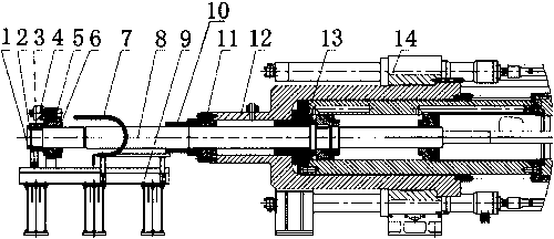
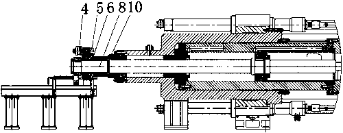
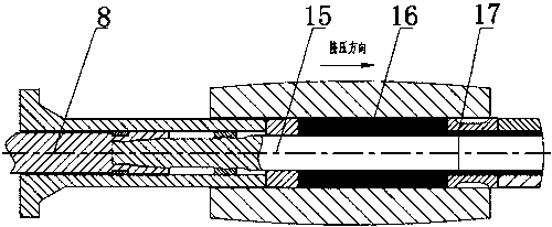
[0019] This embodiment provides an external extrusion device, such as figure 1 and figure 2 As shown, it includes a perforated piston rod 8, a limit sleeve 10, a main cylinder 12, a perforated cylinder 13, a perforated needle 15, an aluminum block 16 and an extrusion die 17, and the described main cylinder 12 is fixedly installed on the extruder frame 14 Above, the main cylinder 12 is fitted with a piercing cylinder 13, a limit sleeve 10 is installed at one end of the main cylinder 12, and an aluminum block 16 and an extrusion die 17 are installed inside the piercing cylinder 13 along its axial direction;
[0020] One end of the perforated piston rod 8 is fixedly connected with the perforated needle 15, and one end of the perforated piston rod 8 on which the perforated needle 15 is installed passes through the spacer sleeve 10, the master cylinder 12 and the perforated cylinder 13 successively, and the other end of the perforated piston rod 8 is sleeved with gear assembly. ...
Embodiment 2
[0024] This embodiment is further detailed on the basis of Embodiment 1. The gear assembly set on the perforated piston rod 8 includes a hydraulic motor 4, a small gear 5 and a large gear 6. The inner ring of the large gear 6 is provided with threads, which are screwed on the On the perforated piston rod 8, the outer ring of the large gear 6 is two stepped surfaces, and the two stepped surfaces are respectively provided with gear teeth and bushings, the hydraulic motor 4 is fixed on the bushing, and the pinion gear 5 is fixed on the output shaft of the hydraulic motor 4 , the gear teeth of the pinion 5 and the bull gear 6 outer ring mesh.
[0025] In the present invention, the limit function formed by the cooperation between the gear assembly and the limit sleeve 10 is a very critical part, and it is a necessary part to realize that the needle head stops when it enters a certain position of the mold. In this embodiment, as the perforating needle 15 advances , the hydraulic mot...
Embodiment 3
[0029] The support assembly 2 includes a fixed sleeve 3 and a support wheel that are set on the perforated piston rod 8. The inner wall of the fixed sleeve 3 and the outer wall of the perforated piston rod 8 are locked and anti-rotated by a flat key in the circumferential direction. The outer lower part of the fixed sleeve 3 is connected to the support wheel by a connecting piece. , the supporting wheel falls on the perforation system guide rail 9.
[0030] The support assembly 2 is located at the outer end of the gear assembly, and a fastening bolt 1 is arranged at the outer end of the support assembly 2 , and the fastening bolt 1 is installed at the end of the perforated piston rod 8 .
[0031] A chain rubber hose 7 is also installed on the guide rail 9 of the perforation system. The control cable of the hydraulic motor 4 is installed in the chain rubber hose 7. The chain rubber hose 7 looks like a tank chain and is composed of many unit links. The links can rotate freely, th...
PUM
 Abstract
Description
Claims
Application Information
 - R&D
- Intellectual Property
- Life Sciences
- Materials
- Tech Scout
- Unparalleled Data Quality
- Higher Quality Content
- 60% Fewer Hallucinations
Browse by: Latest US Patents, China's latest patents, Technical Efficacy Thesaurus, Application Domain, Technology Topic, Popular Technical Reports.
© 2025 PatSnap. All rights reserved.Legal|Privacy policy|Modern Slavery Act Transparency Statement|Sitemap|About US| Contact US: help@patsnap.com