External type mechanical fixed needle extruding device and method

An extrusion device, an external technology, applied in the field of metal extrusion equipment, can solve the problems of increasing the length of the frame, high cost, complex structure, etc. Effect

Inactive Publication Date: 2016-10-12
CHINA NAT HEAVY MACHINERY RES INSTCO
9 Cites 0 Cited by

AI-Extracted Technical Summary

Problems solved by technology

[0003] The built-in mechanical positioning needle needs to increase the perforating moving beam, and at the same time increase the length of the frame, which increases the cost and cost. Due to space constraints, it is difficult to maintain and overhaul, and it is impossible to realize real-time adj...

Method used

In summary, this external mechanical fixed needle extrusion method and device of the present invention can be used for both small and medium-sized presses and large presses, and can adjust the mechanical limit of perforating needles in real time according to the needs of the process. Due to the built-in perforation system and the external part of the mechanical needle positioning, the length of the extruder frame is reduced, the rigidity of the frame is improved, the maintenance is convenient, and the equipment cost is also reduced.
On the perforation system guide rail 9, towline rubber hose 7 is also installed, and the control cable of hydraulic motor 4 is installed in towline rubber hose 7, and towline rubber hose 7 looks like tank chain, is made up of numerous unit links, and rotates ...

Abstract

The invention belongs to the field of metal extrusion equipment, and in particular relates to an external mechanical fixed needle extrusion device and method, including a perforated piston rod, a limit sleeve, a main cylinder, a perforated cylinder, a perforated needle, an aluminum ingot and an extrusion die, the main The cylinder is fixed on the extruder frame, the main cylinder is equipped with a perforated cylinder, and a limit sleeve is installed at one end of the main cylinder, and an aluminum ingot and an extrusion die are installed inside the perforated cylinder along its axial direction; one end of the perforated piston rod is fixed The piercing needle is connected, and one end of the piercing piston rod installed with the piercing needle passes through the limit sleeve, the main cylinder and the piercing cylinder in sequence, and the other end of the piercing piston rod is set with a gear assembly. This external mechanical fixed needle extrusion method and device, It can be used for both small and medium-sized presses and large presses. The mechanical limit position of the perforating needle can be adjusted in real time according to the process needs. Since the perforating system is built-in and the mechanical positioning part is external, the length of the extruder frame is reduced. The rigidity of the frame is improved, the maintenance is convenient, and the equipment cost is also reduced.

Technology Topic

Biomedical engineeringExtrusion +3

Image

  • External type mechanical fixed needle extruding device and method
  • External type mechanical fixed needle extruding device and method
  • External type mechanical fixed needle extruding device and method

Examples

  • Experimental program(4)

Example Embodiment

[0025] Example 1:
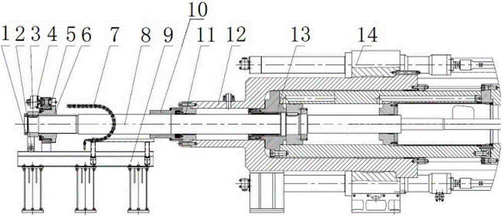
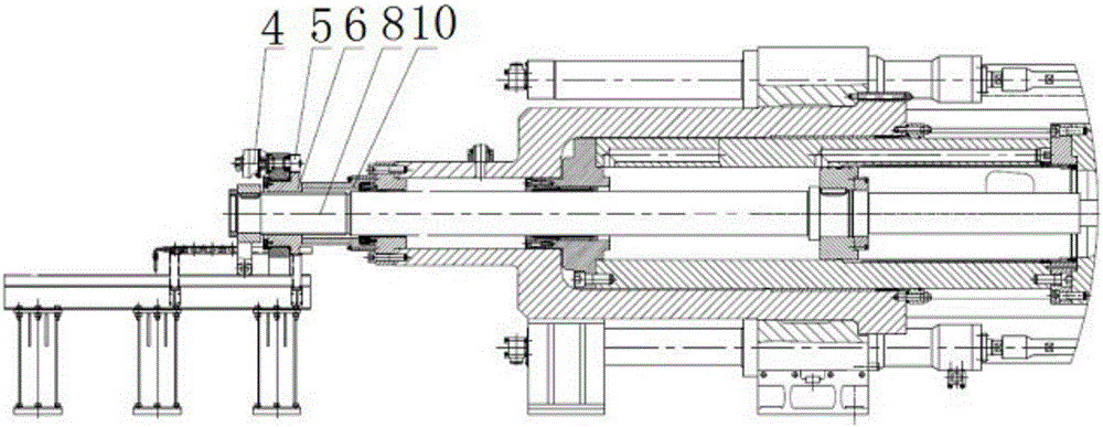
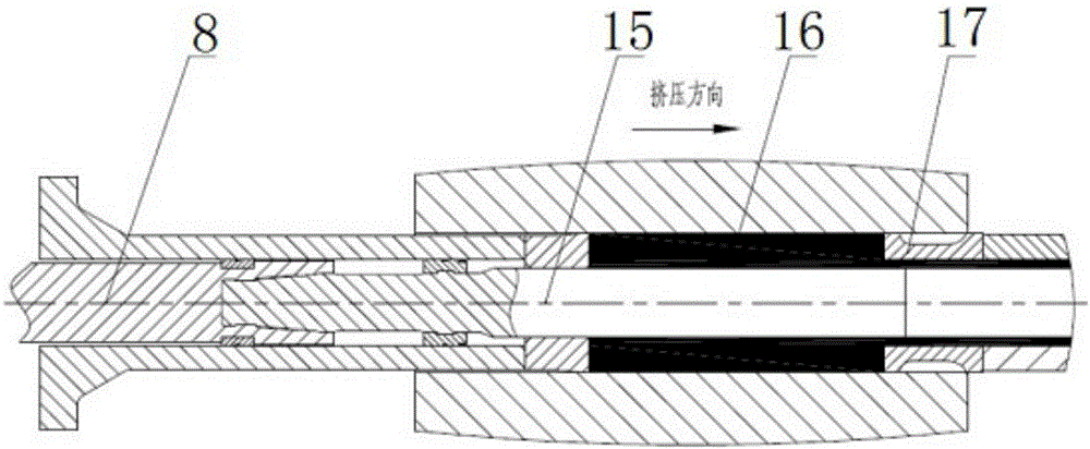
[0026] This embodiment provides an external mechanical fixed needle extrusion device, such as figure 1 with figure 2 As shown, it includes a perforated piston rod 8, a limit sleeve 10, a master cylinder 12, a perforation cylinder 13, a perforation needle 15, an aluminum ingot 16 and an extrusion die 17. The master cylinder 12 is fixedly installed on the extruder frame 14. Above, the main cylinder 12 is sleeved with a perforating cylinder 13, a limit sleeve 10 is installed at one end of the main cylinder 12, and an aluminum ingot 16 and an extrusion die 17 are installed inside the perforating cylinder 13 along its axial direction;
[0027] One end of the perforated piston rod 8 is fixedly connected to the perforating needle 15, one end of the perforated piston rod 8 with the perforating needle 15 passes through the limit sleeve 10, the master cylinder 12 and the perforating cylinder 13 in turn, and the other end of the perforated piston rod 8 is covered with Gear assembly.
[0028] When the fixed needle is squeezed, the piercing system drives the piercing needle 15 forward, the piercing needle 15 advances while the gear assembly rotates, and the position of the gear assembly is adjusted through program control. When the gear assembly contacts the limit sleeve 10, the piercing needle 15 is mechanically Positioning, the needle head of the perforating needle 15 enters the extrusion die 17 for a certain distance and then stops advancing, and the needle is fixed.
[0029] During extrusion, because the friction force of the aluminum ingot 16 on the perforation needle 15 is forward, the contact between the gear assembly and the limit sleeve 10 at this time plays a role in mechanical positioning of the entire perforation system, realizing an external mechanical Fixed needle extrusion method. When the process requires that the position of the perforating needle 15 needs to be changed during the extrusion process, only the position of the gear assembly needs to be adjusted to realize the mechanical fixed needle extrusion again.

Example Embodiment

[0030] Example 2:
[0031] This embodiment is further detailed on the basis of embodiment 1. The gear assembly fitted on the perforated piston rod 8 includes a hydraulic motor 4, a small gear 5 and a large gear 6. The inner ring of the large gear 6 is provided with threads, which are screwed to On the perforated piston rod 8, the outer ring of the large gear 6 has two stepped surfaces, and the two stepped surfaces are respectively provided with gear teeth and a shaft sleeve. The hydraulic motor 4 is fixed on the shaft sleeve, and the pinion gear 5 is fixed on the output shaft of the hydraulic motor 4 , The small gear 5 meshes with the teeth of the outer ring of the large gear 6.
[0032] In the present invention, the limiting function formed by the cooperation between the gear assembly and the limiting sleeve 10 is a very critical part, and it is a necessary component to realize the stop when the needle enters a certain position of the mold. In this embodiment, as the perforating needle 15 advances , The hydraulic motor 4 and the small gear 5 drive the big gear 6 to rotate to adjust the position of the big gear 6 until the big gear 6 contacts the limit sleeve 10 to mechanically fix the perforation system.
[0033] The perforated piston rod 8 is fitted with a support wheel assembly 2 at one end of the gear assembly. The support wheel assembly 2 is installed on the perforated system guide rail 9 and can slide on the guide rail. Such as figure 2 As shown, in the process of advancing, the supporting wheel assembly 2 and the perforating system guide rail 9 play a guiding role for the entire perforating system.
[0034] In this embodiment, since the hydraulic motor 4, the pinion gear 5, the big gear 6, the perforation system guide rail 9 and other perforation system components are all located outside the extruder, the inspection and maintenance are relatively convenient.

Example Embodiment

[0035] Example 3:
[0036] The supporting wheel assembly 2 includes a fixed sleeve 3 and a supporting wheel sleeved on the perforated piston rod 8. The inner wall of the fixed sleeve 3 and the outer wall of the perforated piston rod 8 are locked in a circumferential direction to prevent rotation by a flat key, and the lower part of the fixed sleeve 3 is connected and installed by a connector The supporting wheel falls on the guide rail 9 of the perforation system.
[0037] The support wheel assembly 2 is located at the outer end of the gear assembly, and a lock nut 1 is also provided at the outer end of the support wheel assembly 2, and the lock nut 1 is installed at the end of the perforated piston rod 8.
[0038] The drag chain hose 7 is also installed on the perforation system guide rail 9. The control cable of the hydraulic motor 4 is installed in the drag chain hose 7. The drag chain hose 7 looks like a tank chain and is composed of many unit links, which can rotate freely and the same. The inner height, outer height and pitch of the series of drag chains are the same. The inner width and bending radius R of the drag chains can be different. The unit chain link is composed of left and right chain plates and upper and lower cover plates. Each drag chain can be opened. It is convenient to assemble and disassemble, no need to thread, and the cable can be put into the drag chain after opening the cover. The drag chain hose 7 can protect the cable of the hydraulic motor 4.
[0039] A seal 11 is provided between the master cylinder 12 and the perforated piston rod 8 to prevent hydraulic oil from leaking between the perforated piston rod 8 and the master cylinder 12.

PUM

no PUM

Description & Claims & Application Information

We can also present the details of the Description, Claims and Application information to help users get a comprehensive understanding of the technical details of the patent, such as background art, summary of invention, brief description of drawings, description of embodiments, and other original content. On the other hand, users can also determine the specific scope of protection of the technology through the list of claims; as well as understand the changes in the life cycle of the technology with the presentation of the patent timeline. Login to view more.

Similar technology patents

Front suspension frame for double-body vehicle

Owner:ZHEJIANG GEELY AUTOMOBILE RES INST CO LTD +1

Intelligent storage and transportation system

Owner:GUANGDONG HUANYU ELECTRONICS TECH CO LTD

Flood protective dam and framework thereof

Owner:北京克瑞安邦技术有限公司
Why Eureka
Try Eureka