LED lamp
A technology of LED lamp and LED lamp body, which is applied in the direction of lampshade, lighting and heating equipment, semiconductor devices of light-emitting elements, etc. It can solve the problems of looseness, heat generation of lampshade, cumbersome installation and fixing operation, etc., and achieve low heat and less heat generation Effect
- Summary
- Abstract
- Description
- Claims
- Application Information
AI Technical Summary
Problems solved by technology
Method used
Image

Examples
Embodiment 1
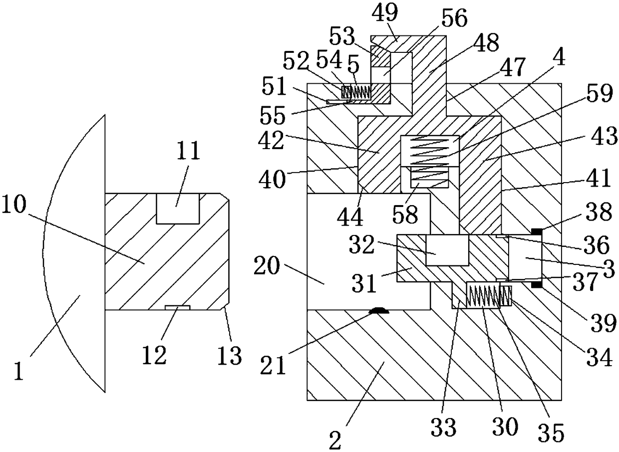
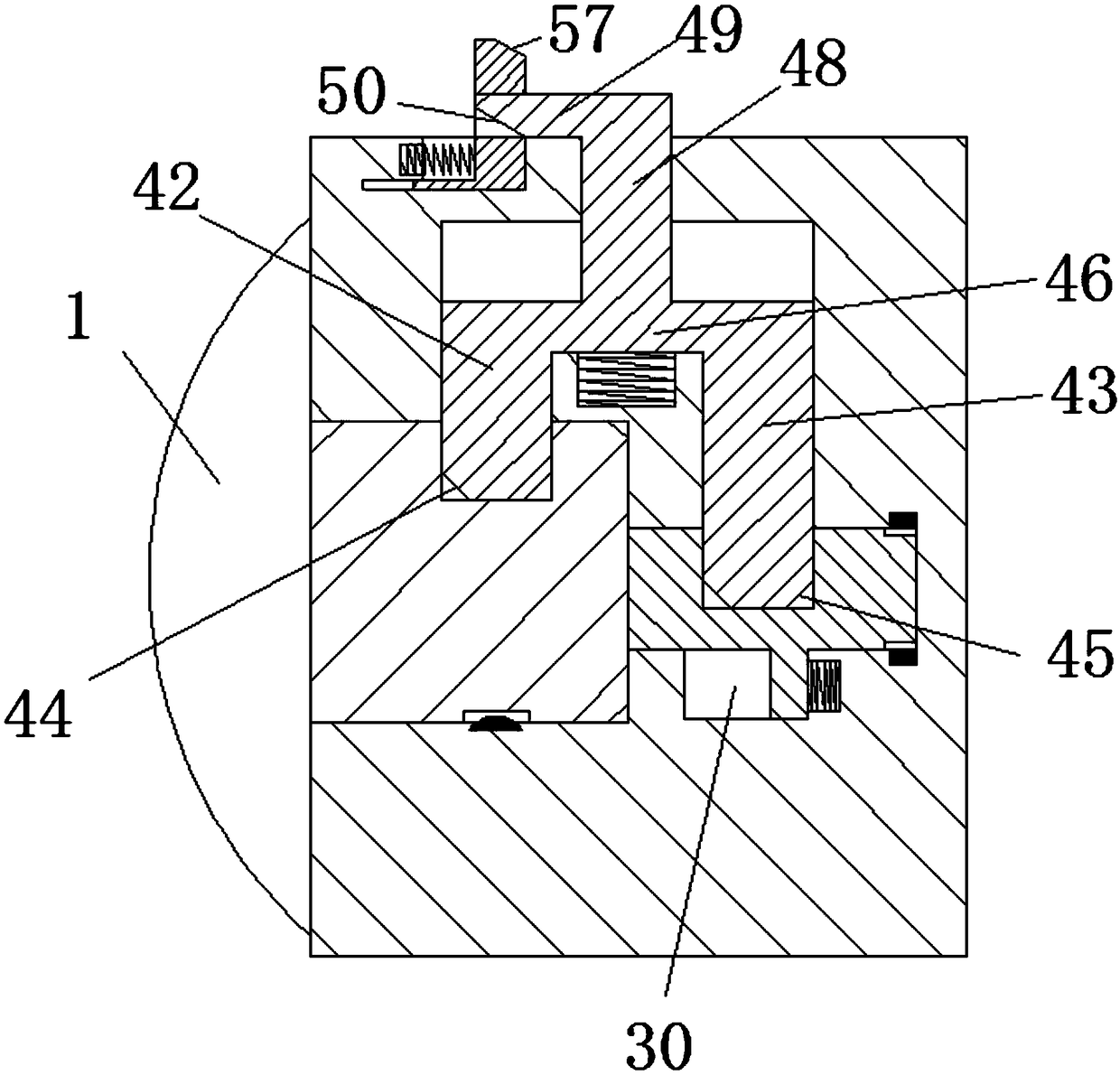
[0025] refer to Figure 1-3 As shown, an LED lamp in this embodiment includes a mounting base 2 and an LED lamp body 1 for mounting on the mounting base 2. A card insertion slot 20 is provided on the left end surface of the mounting base 2. The middle position of the bottom end wall of the card insertion slot 20 is provided with an elastic power supply head 21, the middle position of the top end wall of the card insertion slot 20 is provided with a first longitudinal chute 40, and the right end wall of the card insertion slot 20 is provided with a rightward extending The first transverse chute 3, the top wall of the first transverse chute 3 is provided with a second longitudinal chute 41 extending upwards, the first transverse chute 3 communicates with the second longitudinal chute 41 A second transverse chute 4 is provided, and the top end wall of the second transverse chute 4 is provided with a third longitudinal chute 47 extending upwards out of the mounting base 2, and the...
Embodiment 2
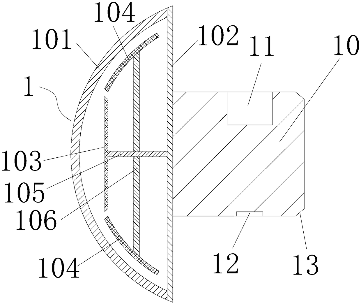
[0043] The difference from Embodiment 1 is that the difference in this implementation lies in the structure of the LED lamp body 1. This embodiment adopts the structure of a double-layer lampshade, combined with Figure 4 As shown, the LED lamp body 1 of this embodiment includes a lamp holder 61, a glass lampshade 62 and a plastic lampshade 63. The lamp holder 61 has a first side 64 and a second side 65 oppositely arranged, and the first side 64 is provided with a hemispherical lamp board 66, the hemispherical lamp board 66 is welded on the first side 64 of the lamp holder 61, the hemispherical lamp board 66 is provided with several LED lamp beads, and several LED lamp beads are arranged on the outer surface of the hemispherical lamp board 66, the glass lampshade 62 and the plastic The lampshade 63 is hermetically connected to the first side 64 of the lamp holder 61, and the glass lampshade 62 is arranged on the outside of the hemispherical lamp plate 66, the plastic lampshade ...
Embodiment 3
[0049] The difference from the second embodiment is that the difference in this implementation is that a support frame 70 is provided in the vacuum chamber 67, combined with Figure 5 As shown, since both the plastic lampshade 63 and the glass lampshade 62 will be deformed due to ambient temperature or heat, in this embodiment, a supporting frame 70 is provided in the vacuum chamber 67, and one end of the supporting frame 70 is in contact with the glass lampshade 62, and the supporting frame The other end of 70 is in contact with the plastic lampshade 63, and the supporting frame 70 is elastic. In order to prevent the supporting frame 70 from sliding freely, an outer supporting groove 71 is provided on the outer wall of the glass lampshade 62 in this embodiment, and the supporting frame 70 is in contact with the glass lampshade. One end of 62 extends into the outer support groove 71 , the inner wall of the plastic lampshade 63 is provided with an inner support groove 72 , and o...
PUM
 Abstract
Description
Claims
Application Information
 - R&D
- Intellectual Property
- Life Sciences
- Materials
- Tech Scout
- Unparalleled Data Quality
- Higher Quality Content
- 60% Fewer Hallucinations
Browse by: Latest US Patents, China's latest patents, Technical Efficacy Thesaurus, Application Domain, Technology Topic, Popular Technical Reports.
© 2025 PatSnap. All rights reserved.Legal|Privacy policy|Modern Slavery Act Transparency Statement|Sitemap|About US| Contact US: help@patsnap.com