Firing pin type firing mechanism achieving clear sensing function and ready-to-fire state indicating function

A firing mechanism and firing pin technology, which is applied to firing/trigger mechanisms, weapon accessories, offensive equipment, etc., can solve the problems of no indication features and inconspicuous perceptible features of firing pin pistols to be fired, and achieve a simple assembly process. , a small number of effects

Active Publication Date: 2019-02-22
CHONGQING JIANSHE IND GRP
View PDF3 Cites 2 Cited by
  • Summary
  • Abstract
  • Description
  • Claims
  • Application Information

AI Technical Summary

Problems solved by technology

[0003] The purpose of the present invention is to provide a firing pin firing mechanism with a ready-to-fire indication function with obvious perceivable features, aiming at the problem that the firing state of the firing pin pistol has no indication feature or the perceivable feature is not obvious

Method used


Image

  • Firing pin type firing mechanism achieving clear sensing function and ready-to-fire state indicating function
  • Firing pin type firing mechanism achieving clear sensing function and ready-to-fire state indicating function
  • Firing pin type firing mechanism achieving clear sensing function and ready-to-fire state indicating function

Examples


Embodiment Construction

[0029] The present invention will be described in detail below in conjunction with the embodiments and the accompanying drawings.

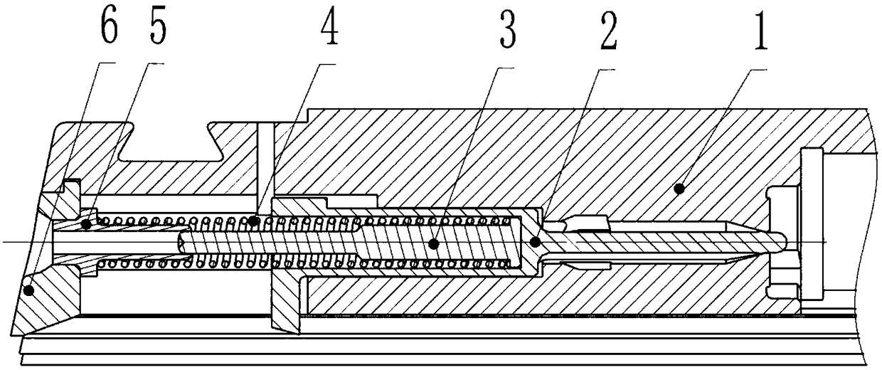
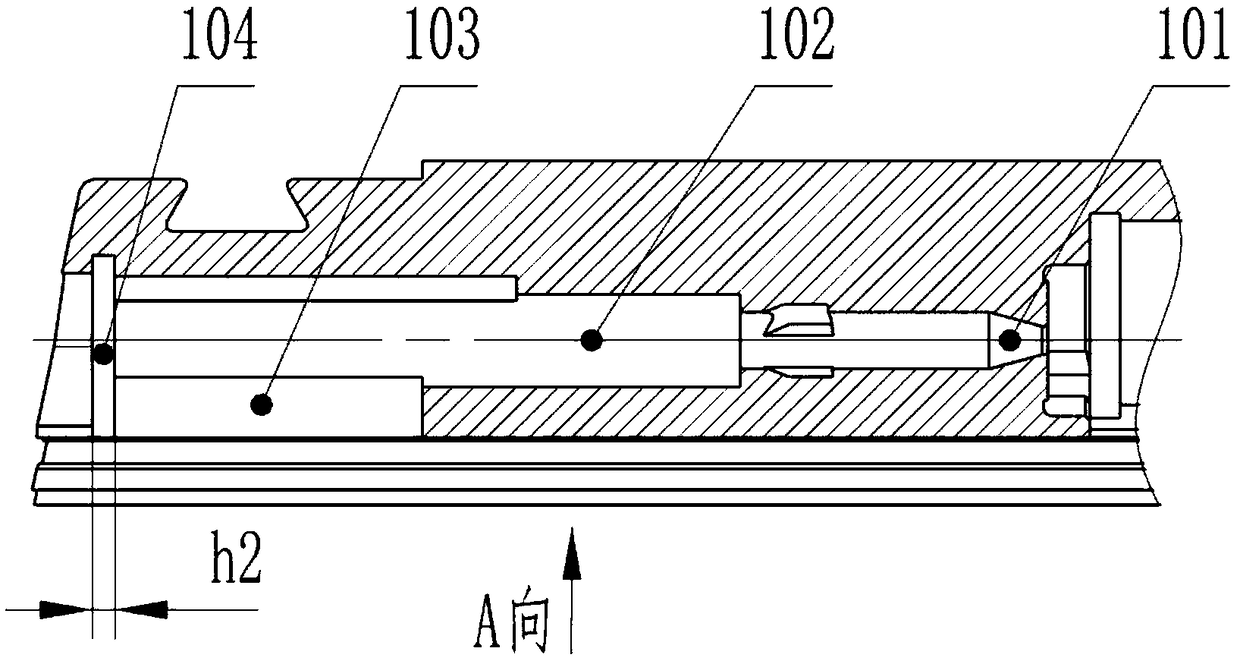
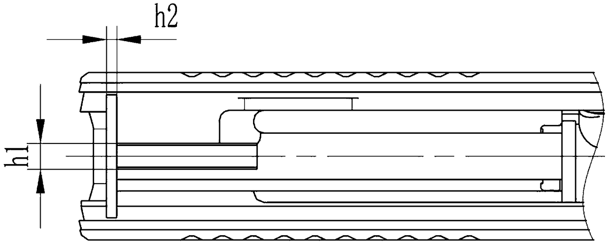
[0030] Such as Figure 1-Figure 13 As shown, an embodiment of a firing pin firing mechanism with a clearly perceivable ready-to-fire indication function includes a bolt 1, and a firing pin hole 102 is arranged inside the bolt 1, and the firing pin hole 102 includes sequentially from front to back. The setting cone hole 101 before the firing pin, the relief slot hole 103 for the firing pin tooth and the slot hole 104 of the bolt baffle, also include the firing pin 2 which is matched with the positioning cone hole 101 before the firing pin, and is installed on the bolt baffle. The trigger baffle plate 6 in the slot hole 104, the rear end of the firing pin 2 is provided with a firing pin spring container spring hole 202, and the firing pin spring container spring hole 202 is provided with a firing pin spring guide rod 3, which is sleeved on the firin...


PUM


Abstract

The invention discloses a firing pin type firing mechanism achieving the clear sensing function and the ready-to-fire state indicating function. The firing pin type firing mechanism achieving the clear sensing function and the ready-to-fire state indicating function comprises a gunlock. Firing pin holes are formed in the gunlock and sequentially comprise a firing pin front locating conical hole, afiring pin tooth recession groove hole and a gunlock baffle insertion groove hole from front to back. The firing pin type firing mechanism achieving the clear sensing function and the ready-to-fire state indicating function further comprises a firing pin matched with the firing pin front locating conical hole and a gunlock baffle installed in the gunlock baffle insertion groove hole. The back endof the firing pin is provided with a firing pin spring containing hole. A firing pin spring guide rod and a firing pin spring arranged on the firing pin spring guide rod in a sleeving manner are arranged in the firing pin spring containing hole. The gunlock baffle is provided with a locating hole penetrating through the front and back sides. A hollow firing pin spring seat is installed in the locating hole. The outer circumferential face of the firing pin spring seat is provided with a first step abutting against the firing pin spring in a connected manner. The firing pin spring guide rod isprovided with a second step abutting against the firing pin spring and used for limiting the firing pin spring in a front-back direction. The back end of the firing pin spring guide rod is in slidingfit in the firing pin spring seat. When a backseat of the gunlock is in place, the back end of the firing pin spring guide rod extends out of the gunlock baffle.

Description

technical field [0001] The invention relates to the field of firearm structure design, in particular to a firing mechanism of a striker-type pistol with a clearly perceivable ready-to-fire indication function. Background technique [0002] In the last century, except for the Glock pistol, the mainstream pistols in the world were all based on the hammer-type percussion. obvious. However, it also brings about an inherent disadvantage of the hammer-type firing mechanism, that is, the exposed hammer makes it difficult to shorten the length of the gun, and the hammer that falls backwards when the gun is released is prone to hooking. In view of this, entering this century, especially in recent years, major light weapons manufacturers in the world have abandoned hammer-type firing mechanisms one after another, and launched a variety of firing pin-type pistols, making firing-pin-type pistols come from behind. The striker-type firing mechanism has few parts, and the parts are insta...

Claims


Application Information

Patent Timeline
Patent Type & Authority Applications(China)
IPC IPC(8): F41A19/13F41A19/34
CPCF41A19/13F41A19/34
Inventor 徐伏波郭新朋谢凤罗浩然李良刚赵渝江王明君周云飞周飞
Owner CHONGQING JIANSHE IND GRP
Why Eureka
Try Eureka