Light control structure, display device and working method

A light control and display device technology, applied in optics, nonlinear optics, instruments, etc., can solve problems such as low brightness, affecting the driver's vision, color shift, etc., and achieve the effect of enhancing display brightness and enhancing visibility

Active Publication Date: 2019-02-22
BOE TECH GRP CO LTD
View PDF6 Cites 2 Cited by
  • Summary
  • Abstract
  • Description
  • Claims
  • Application Information

AI Technical Summary

Problems solved by technology

[0002] Existing car display screens often have the problem of low brightness and color shift when viewed from a large vie

Method used


Image

  • Light control structure, display device and working method
  • Light control structure, display device and working method
  • Light control structure, display device and working method

Examples


Example Embodiment

[0039] In order to make the technical problems, technical solutions, and advantages to be solved by the embodiments of the present invention clearer, a detailed description will be given below with reference to the drawings and specific embodiments.
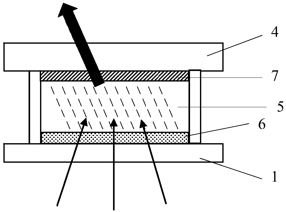
[0040] The embodiments of the present invention provide a light control structure, a display device and a working method, which can control the direction of light emission of the display screen.

[0041] The embodiment of the present invention provides a light control structure, including:

[0042] First electrode

[0043] Second electrode

[0044] A two-dimensional material layer located between the first electrode and the second electrode, the long axis direction of the two-dimensional material in the two-dimensional material layer is affected by the electric field between the first electrode and the second electrode control.

[0045] In this embodiment, the light control structure includes a first electrode, a second electrode, and a tw...


PUM

PropertyMeasurementUnit
Widthaaaaaaaaaa
Thicknessaaaaaaaaaa

Abstract

The invention provides a light control structure, a display device and a working method, and belongs to the technical field of display. The light control structure includes: a first electrode; a second electrode; and a two-dimensional material layer positioned between the first electrode and the second electrode, wherein the long axis direction of the two-dimensional material in the two-dimensional material layer is controlled by an electric field between the first electrode and the second electrode. According to the technical scheme of the light control structure, display device and working method, the emergent direction of the light rays of the display screen can be controlled.

Description

technical field [0001] The invention relates to the field of display technology, in particular to a light control structure, a display device and a working method. Background technique [0002] Existing vehicle-mounted display screens often have the problems of low brightness and color shift when the emitted light is irradiated on the vehicle's windshield and affects the driver's field of vision. Contents of the invention [0003] The technical problem to be solved by the present invention is to provide a light control structure, a display device and a working method capable of controlling the outgoing direction of light from a display screen.
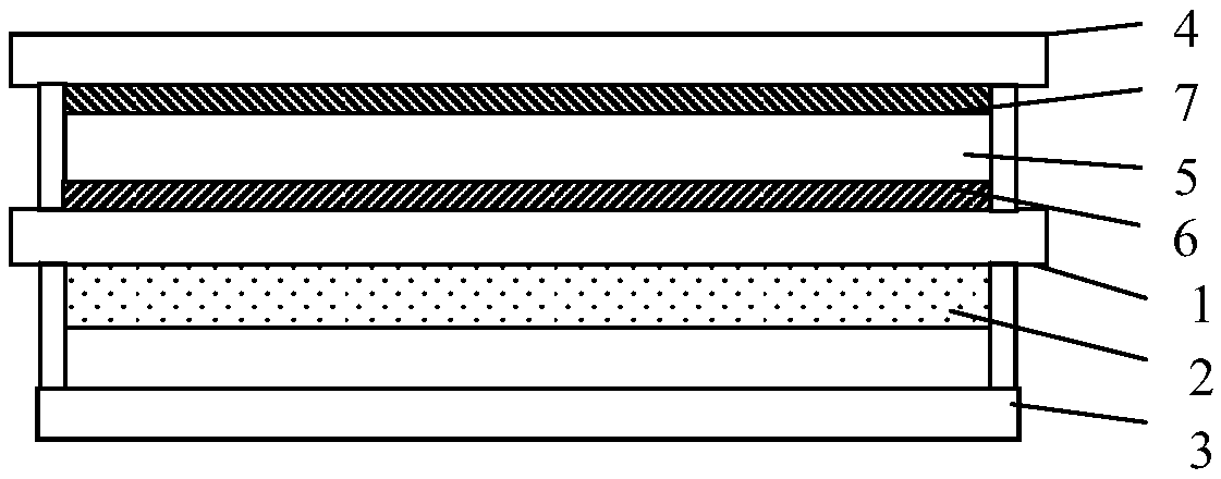
 [0004] In order to solve the above technical problems, embodiments of the present invention provide technical solutions as follows: [0005] In one aspect, a light control structure is provided, including: [0006] first electrode; [0007] second electrode; [0008] A two-dimensional material layer located between the first el...

Claims


Application Information

Patent Timeline
IPC IPC(8): G02F1/01
CPCG02F1/0102G02F1/0121
Inventor 孙海雁李锐刘明星赵伟利于美娜
Owner BOE TECH GRP CO LTD
Why Eureka
Try Eureka