Sound emitting device

A technology for sound-emitting devices and components, applied in the field of acoustics and electricity, can solve the problems of voice coil design limitations, limited acoustic improvement of sound-emitting devices, and limited volume of magnetic circuit systems, achieving lateral swing suppression, overall lightness and thinness, and improved acoustics. performance effect

Active Publication Date: 2019-02-22
AAC TECH PTE LTD
View PDF10 Cites 3 Cited by
  • Summary
  • Abstract
  • Description
  • Claims
  • Application Information

AI Technical Summary

Problems solved by technology

[0004] However, in the sound-generating device in the related art, the diaphragm and the elastic support assembly are respectively fixed on the opposite ends of the voice coil, although the elastic support assembly can effectively prevent the lateral vibration of the voice coil swing, but its structure directly connected to the voice coil leads to the restriction of the design of the voice coil, and the volume of the magnetic circuit system is also limited, so that the improvement of the acoustic performance of the sound-generating device is limited

Method used


Image

  • Sound emitting device
  • Sound emitting device
  • Sound emitting device

Examples


Embodiment Construction

[0039] The following will clearly and completely describe the technical solutions in the embodiments of the present invention with reference to the accompanying drawings in the embodiments of the present invention. Obviously, the described embodiments are only some, not all, embodiments of the present invention. Based on the embodiments of the present invention, all other embodiments obtained by persons of ordinary skill in the art without making creative efforts belong to the protection scope of the present invention.

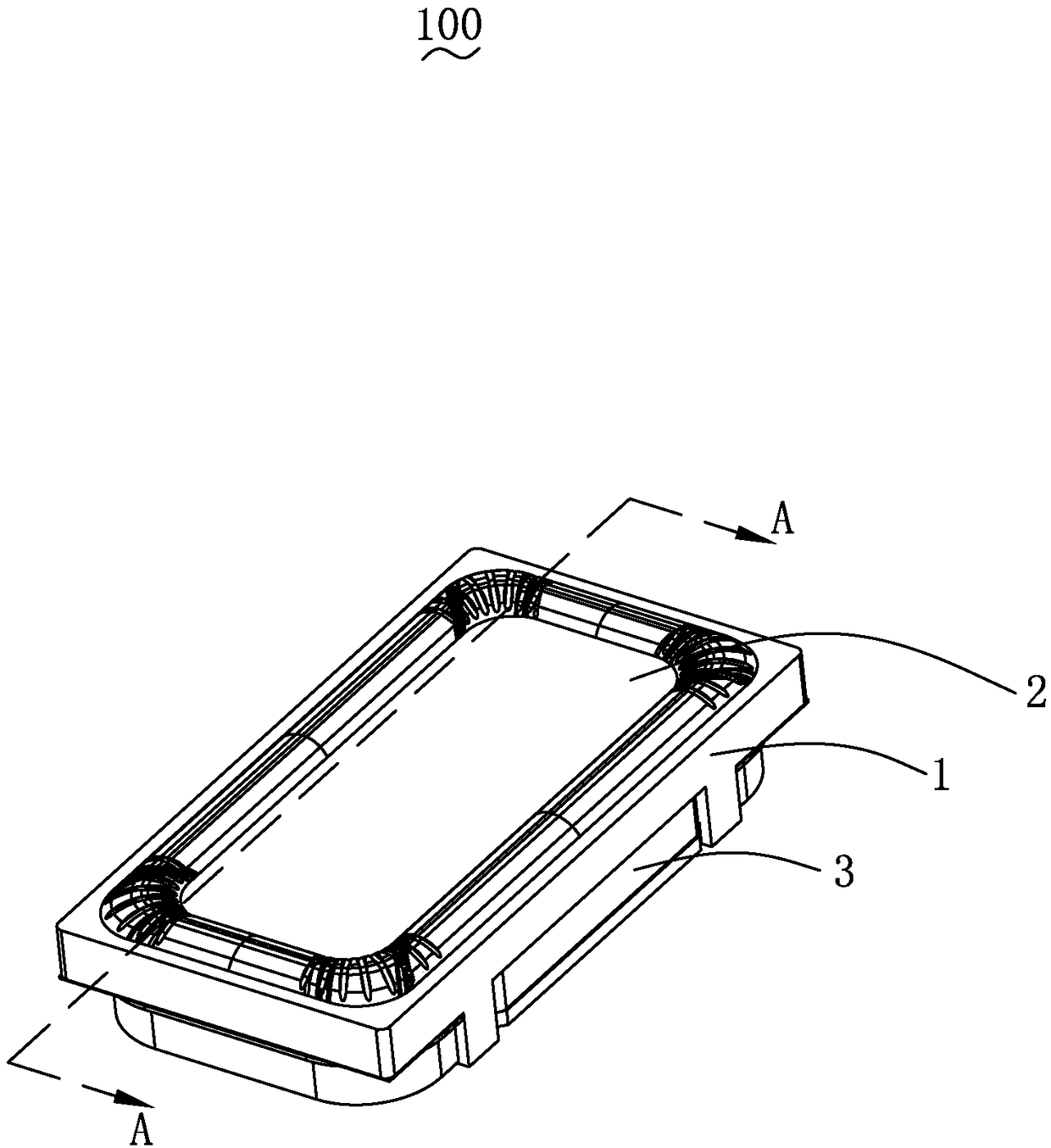
[0040] see figure 1 As shown, the present invention provides a sound emitting device 100 , which includes a basin frame 1 , a vibration system 2 and a magnetic circuit system 3 .

[0041] The pot frame 1 is used for fixedly supporting the vibrating system 2 and the magnetic circuit system 3 .

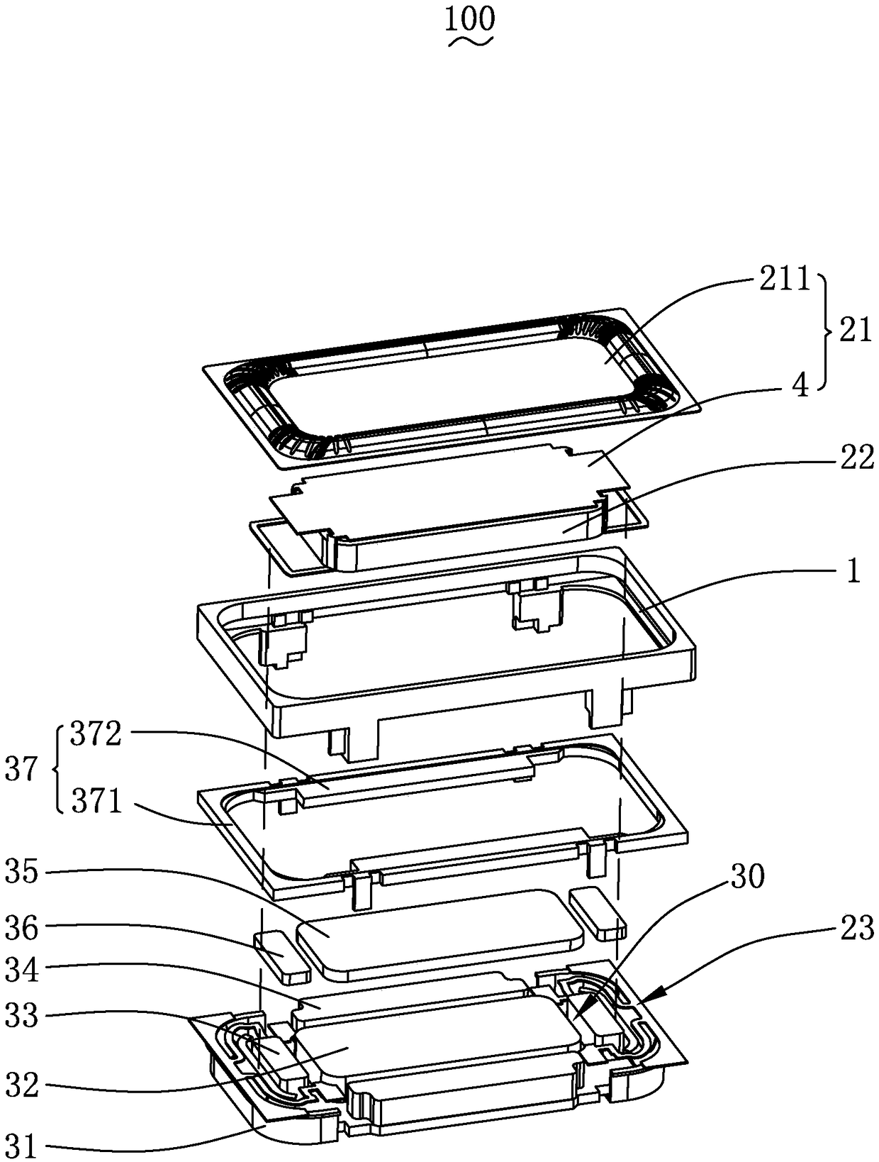
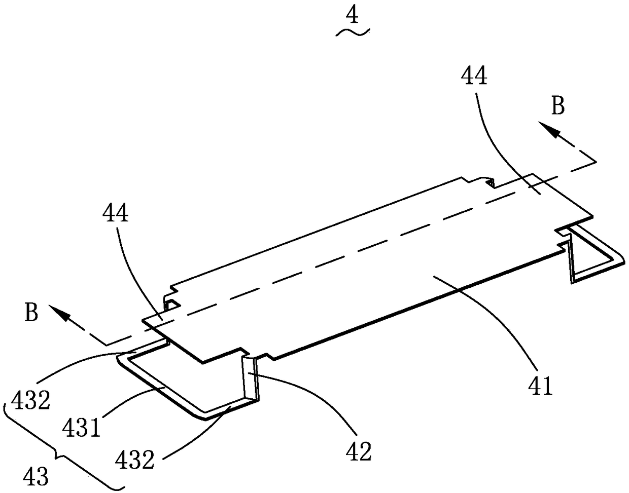
[0042] see Figure 2-4As shown, the vibration system 2 includes a diaphragm 21 fixed to the frame 1, a voice coil 22 that drives the diaphragm 21 to vibrate and sound...


PUM


Abstract

The invention provides a sound emitting device. The sound emitting device comprises a basin frame, and a vibration system and a magnetic circuit system with a magnetic gap separately fixed to the basin frame; the vibration system includes a vibrating diaphragm fixed to the basin frame, a voice coil inserted in the magnetic gap to drive the vibration and sound emitting of the vibrating diaphragm, and an elastic support assembly fixed to the basin frame and arranged opposite to the vibrating diaphragm, which is characterized in that: a side of the vibrating diaphragm adjacent to the voice coil extends toward the voice coil to form a first wall, and a distal end of the first wall is bent and extended to form a second wall; the second wall is connected to the voice coil through the first wall,and the second wall is connected to the elastic support assembly and spaced from the voice coil; the first wall is connected to the side of the voice coil; and the first wall and the second wall areused to elastically suspend the voice coil below the vibrating diaphragm. Compared with the related art, the sound emitting device provided by the invention has good acoustic performance and high reliability.

Description

【Technical field】 [0001] The invention relates to the field of sound and electricity, in particular to a sound generating device used in portable electronic products. 【Background technique】 [0002] With the advent of the mobile Internet era, the number of smart mobile devices continues to rise. Among the many mobile devices, the mobile phone is undoubtedly the most common and portable mobile terminal device. Sound-generating devices for playing sound are widely used in smart mobile devices such as mobile phones. [0003] The sound-generating device in the related art includes a pot frame, a vibration system respectively fixed to the pot frame, and a magnetic circuit system with a magnetic gap; the vibration system includes a diaphragm fixed to the pot frame, The diaphragm is inserted into the magnetic gap to drive the diaphragm to vibrate and produce sound, and one end is fixed to the frame, and the other end is fixed to the elastic support component of the end of the voi...

Claims


Application Information

Patent Timeline
Patent Type & Authority Applications(China)
IPC IPC(8): H04R9/06H04R9/02
CPCH04R9/025H04R9/06H04R2400/11
Inventor 令狐荣林刘晓东肖波
Owner AAC TECH PTE LTD
Why Eureka
Try Eureka