Soundproofing panel with beads, and a method of manufacture

a technology of soundproofing panels and beads, applied in the field of soundproofing panels, can solve the problems of difficult adaptation to soundproofing panels, poor thermal behavior of soundproofing panels, etc., and achieve the effect of reducing such drawbacks and improving acoustic performan

Active Publication Date: 2009-04-21
ATECA +1
View PDF16 Cites 24 Cited by
  • Summary
  • Abstract
  • Description
  • Claims
  • Application Information

AI Technical Summary

Benefits of technology

[0010]The present invention thus seeks to mitigate such drawbacks by proposing a soundproofing panel that withstands high temperatures, that has improved acoustic performance, and that can present acoustic characteristics that vary.
[0015]The use of beads with walls that are porous and micro-perforated has the advantage of significantly increasing the viscothermal effect on the air compared with beads that are not micro-perforated. Micro-perforating the walls of the hollow beads enables the insides of the beads to participate in passing molecules of air in the same manner as the interstitial network.
[0017]As a result, the acoustic effectiveness of the panel of the invention is increased for given size compared with a conventional panel, and this gives rise to a sound-absorption band that is broader in terms of frequency. Likewise, for similar acoustic performance, the soundproofing panel of the invention can achieve space savings.
[0018]Use of metal nets for holding the beads in place instead of using a binder also presents numerous advantages. In particular, this makes it simpler to manufacture the soundproofing panel and makes it possible locally to vary its acoustic characteristics (varying the thickness of the layer within a given cell, mixing different types of spheres, . . . ), and to adapt those characteristics to requirements, e.g. on the basis of angular or radial sectors.
[0019]It is advantageous to use nets having the same compositions as the partitions to which they are secured, which can make it possible to avoid problems of heterogeneous coupling that lead to corrosion. It is also possible to obtain a one-piece soundproofing panel that is circularly symmetrical.
[0021]In addition, the sound energy dissipating layers may be of thickness that is constant or that varies within a given cell. As explained above, these advantageous characteristics make it possible to cause the acoustic characteristics of the soundproofing panel to vary.

Problems solved by technology

Apart from the difficulty in making it, the soundproofing panel described in that patent presents certain other drawbacks for applications at high temperature.
That soundproofing panel presents poor thermal behavior when it is subjected to high temperatures, and the use of a binder between the beads leads to problems of galvanic coupling, leading in turn to problems with points of corrosion.
In addition, when processing using cavities of large dimensions, the method disclosed is difficult to adapt to implementing soundproofing panels with acoustic characteristics that vary.

Method used


Image

  • Soundproofing panel with beads, and a method of manufacture
  • Soundproofing panel with beads, and a method of manufacture
  • Soundproofing panel with beads, and a method of manufacture

Examples


Embodiment Construction

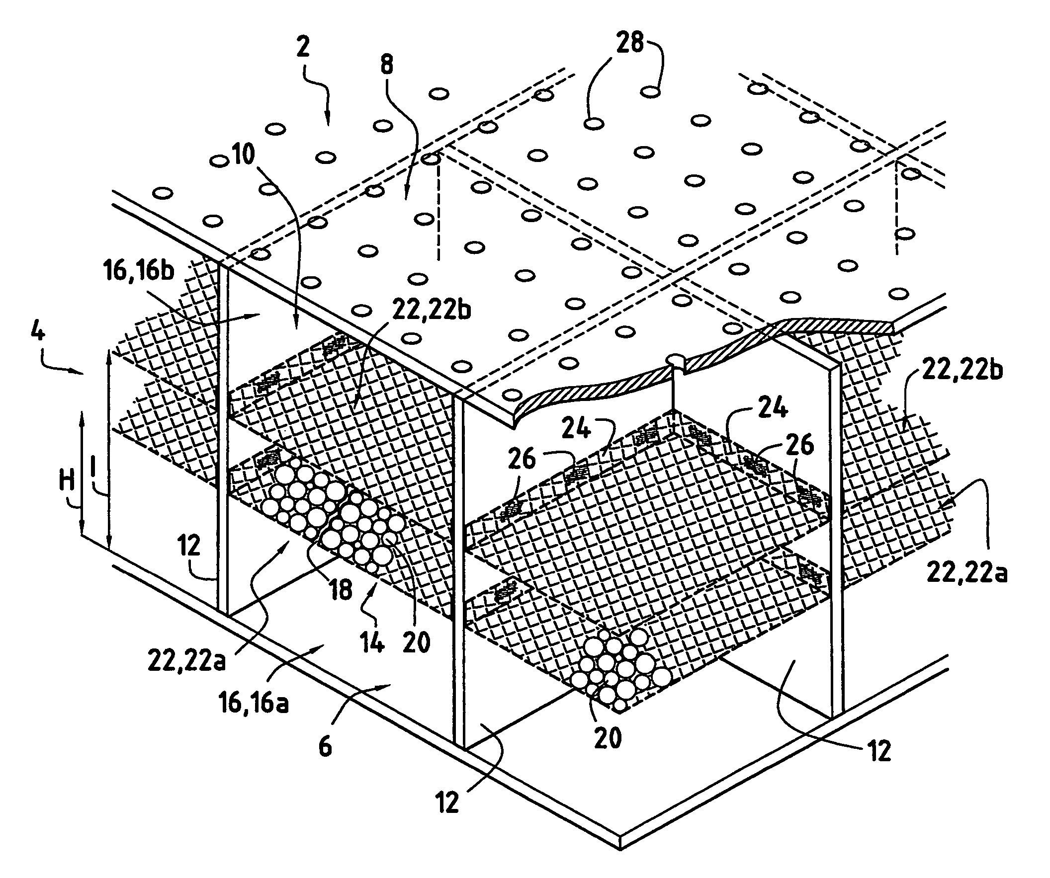
[0033]Reference is made initially to FIG. 1 which is a perspective view of a soundproofing panel in an embodiment of the invention.

[0034]The soundproofing panel 2 is a structure comprising a core 4 sandwiched between a solid wall (or skin) 6 and a porous wall (or skin) 8. The core 4 of the panel is constituted by a plurality of cells 10 that are separated by partitions 12 extending in the thickness direction of the core, perpendicularly to the walls 6 and 8.

[0035]The cells may be of rectangular section (as shown in FIG. 1), or they may be of triangular or hexagonal section, for example.

[0036]The partitions 12 are fixed to the walls 6 and 8, e.g. by welding, so as to form the structure of the soundproofing panel and so as to ensure that it is rigid and strong.

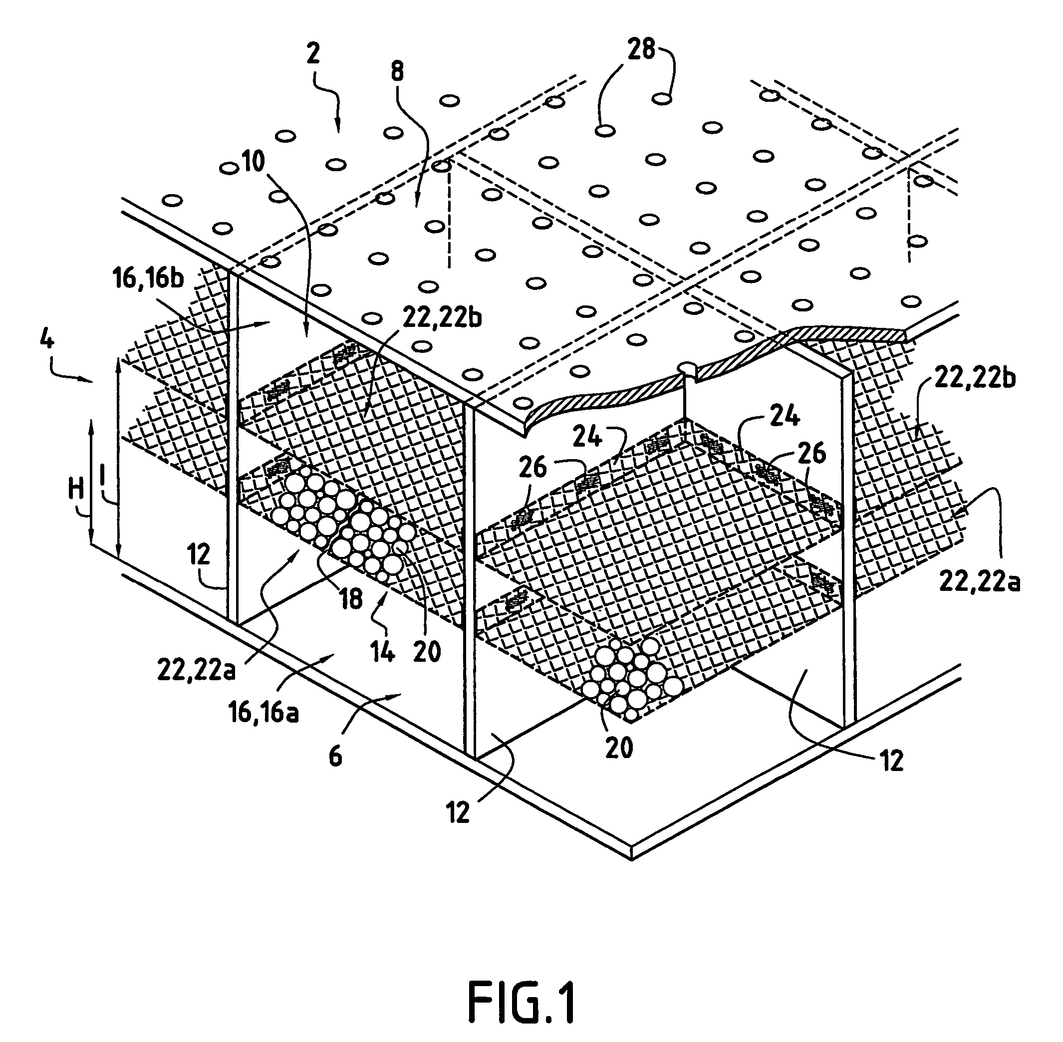
[0037]Each cell 10 formed in this way is subdivided in the thickness direction of the core 4 by at least one sound energy dissipating layer 14 whose edges are secured to the partitions 12.

[0038]The dissipating layers 14 subdivid...


PUM


Abstract

A soundproofing panel having a core sandwiched between a solid wall and a porous wall. The core being connected to the walls and having partitions extending in the thickness direction between the two walls so as to form cells. Each cell containing at least one sound energy dissipating layer constituted by hollow spherical beads having mutually contacting walls that are porous and micro-perforated, and being held in position in the thickness direction between the two walls by nets that are secured to the partitions.

Description

BACKGROUND OF THE INVENTION[0001]The present invention relates to the general field of soundproofing panels of the so-called “passive” type operating on the basis of Helmholtz resonators.[0002]It finds an advantageous application in the aviation sector, in particular for the ducts of a turbomachine that are subjected to high temperatures.[0003]In the field of aviation, soundproofing panels are used to reduce the level of sound emitted by the turbomachines of an airplane. These panels are generally disposed directly as flow walls in order to attenuate the sound energy generated by the various components of the turbomachine.[0004]The present invention seeks more particularly to apply such soundproofing panels to the hot ducts of a turbomachine, for example at turbine outlets or at the exhaust nozzle.[0005]In this context, it is therefore necessary to make soundproofing panels that withstand the high temperatures of the ducts and that enable sound levels to be reduced without thereby p...

Claims


Application Information

Patent Timeline
Patent Type & Authority Patents(United States)
IPC IPC(8): E04B1/84B64D29/00F02C7/00F01D25/30F02C7/24F02K1/44G10K11/16G10K11/165G10K11/172
CPCB64D29/00G10K11/172
Inventor DRAVET, ALAINRIOU, GEORGESJULLIARD, JACQUESDELVERDIER, OSMINVIE, PHILIPPE
Owner ATECA
Why Eureka
Try Eureka