Electrical connector

A technology of electrical connectors and connecting parts, applied in the direction of connection, two-part connection device, circuit, etc., can solve the problems of cross-talk interference and affect the high-frequency performance of electrical connectors, and achieve the effect of reducing cross-talk interference

Active Publication Date: 2019-02-26
DEYI PRECISION ELECTRONIC IND CO LTD PANYU
View PDF6 Cites 5 Cited by
  • Summary
  • Abstract
  • Description
  • Claims
  • Application Information

AI Technical Summary

Problems solved by technology

[0003] However, the rear end of the shielding sheet in the prior art does not exceed the insulating block backwards, so that there is no shielding sheet between the upper and lower rows of second conducting parts for shielding, resulting in crosstalk interference between the upper and lower rows of terminals, Affect the high frequency performance of electrical connectors

Method used


Image

  • Electrical connector
  • Electrical connector
  • Electrical connector

Examples


Embodiment Construction

[0037] In order to facilitate a better understanding of the purpose, structure, features, and effects of the present invention, the present invention will now be further described in conjunction with the accompanying drawings and specific embodiments.

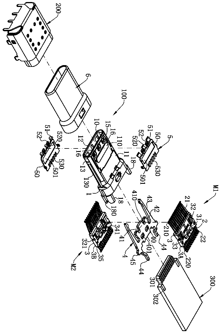
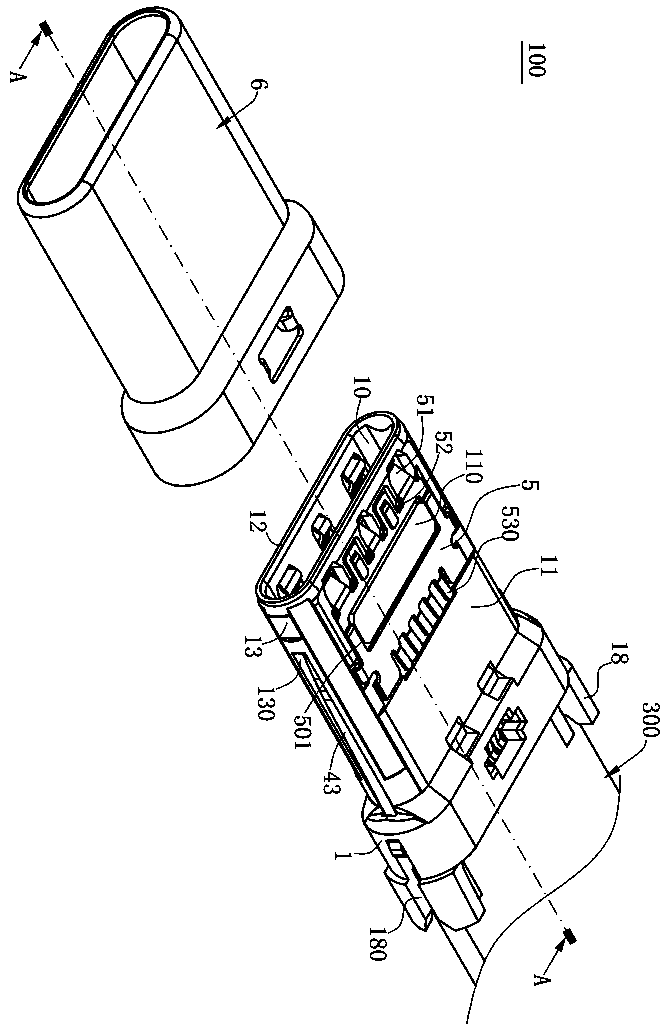
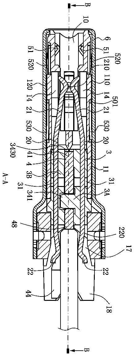
[0038] see figure 1 , figure 2 with image 3 , this is an electrical connector 100 of the embodiment of the present invention, the electrical connector 100 of this embodiment is a TYPE C plug connector, the electrical connector 100 is docked with a socket connector 200 forward, and installed backward on a circuit board 300 . The electrical connector 100 includes an insulating body 1, and the insulating body 1 contains a first terminal module M1, a second terminal module M2 and a shielding sheet 4, and the shielding sheet 4 is placed on the first terminal module M1. and the second terminal module M2. The two ground plates 5 are 180° symmetrical up and down, covering the upper and lower surfaces of the insulating body 1 resp...


PUM


Abstract

The invention discloses an electrical connector, which is used for electrically conducting a first component and a second component. The electrical connector comprises: an insulating block; a plurality of terminals which are arranged in an upper row and a lower row, each terminal having a horizontal section fixed in the insulating block, a first conductive portion extending forward from the horizontal section for electrically conducting the first component, and a second conductive portion extending rearward from the horizontal section, wherein the second conductive portion has a bent portion connected to the horizontal section; and a shield plate fixed to the insulating block and positioned between two rows of terminals. The rear end of the shield plate is provided with an abutment part for abutting on the second component. The abutment part extends backward out of the insulating body and does not exceed the bent part.

Description

technical field [0001] The invention relates to an electrical connector, in particular to a high-frequency electrical connector. Background technique [0002] A conventional electrical connector is used to electrically connect a receptacle connector and a circuit board, including an insulating body, two terminal modules, a shielding sheet and a metal shell, wherein each terminal module includes an insulating block and is located on A row of terminals of the insulating block is used to transmit high-speed signals, each of the terminals has a fixed part, the fixed part is embedded in the insulating block, a contact part extends forward from the fixed part, and is in electrical contact with the plug connector, A welding part is extended backward from the fixing part, and the welding part extends backward to form an insulating block and an insulating body, and is electrically connected to the circuit board. The two terminal modules clamp the shielding sheet up and down and are ...

Claims


Application Information

Patent Timeline
Patent Type & Authority Applications(China)
IPC IPC(8): H01R12/70H01R13/646H01R13/20H01R13/15H01R13/629H01R13/639
CPCH01R12/7011H01R13/15H01R13/20H01R13/629H01R13/639H01R13/6461H01R13/6585H01R13/6594H01R24/60H01R13/502H01R13/6273
Inventor 刘军
Owner DEYI PRECISION ELECTRONIC IND CO LTD PANYU
Why Eureka
Try Eureka