Electrical connector for reducing high frequency crosstalk interferences

a technology of crosstalk interference and electrical connector, which is applied in the direction of coupling device connection, two-part coupling device, electrical apparatus, etc., can solve the problems of crosstalk interference between signal terminals and serious effects, and achieve the effect of reducing crosstalk interference and high frequency crosstalk interferen

Inactive Publication Date: 2014-12-30
CONCRAFT HLDG
View PDF4 Cites 2 Cited by
  • Summary
  • Abstract
  • Description
  • Claims
  • Application Information

AI Technical Summary

Benefits of technology

[0008]Accordingly, an embodiment of the disclosure introduces an electrical connector for reducing high frequency crosstalk interferences, which is provided to insert with at least two mating elements. The electrical connector includes a first joint, a first signal terminal, a second joint, a second signal terminal and a ground terminal. The first joint is used to be inserted by one of the mating elements. The first signal terminal is electrically connected with the mating element inserted within the first joint. The second joint is used to be inserted by another mating element. The second signal terminal is electrically connected with the mating element inserted within the second joint. The ground terminal is electrically connected with the first joint and the second joint, and disposed between the first signal terminal and the second signal terminal. Signal flow spaces located between the ground terminal and respectively the first signal terminal and second signal terminals are used as signal flow paths for the first signal terminal and second signal terminal respectively.
[0010]In an embodiment, RCA connector is preferably used as an explanatory example of an electrical connector for reducing high frequency crosstalk interferences, and used for inserting with AV terminals (so-called Composite video connector).
[0011]The advantage for the electrical connector according to the embodiments of the disclosure is to dispose a ground terminal between different signal terminals. The ground terminal may be integrally formed and connected with each of the signal joints; or multiple ground terminals may be respectively connected with their corresponding signal joints. The signal flow spaces formed between the ground terminals with each of the signal terminals may be used as signal flow paths for the first signal terminal and the second signal terminal. Here each of the signal flow spaces is independent to each other, so as to reduce the crosstalk interferences between the adjacent signal terminals during high-speed signal transmission.

Problems solved by technology

In other words, crosstalk interferences are incurred between the signal terminals inside the connector.
However, if the connector is used for high-speed signal transmission, the crosstalk interferences between signal terminals causes serious effects.

Method used


Image

  • Electrical connector for reducing high frequency crosstalk interferences
  • Electrical connector for reducing high frequency crosstalk interferences
  • Electrical connector for reducing high frequency crosstalk interferences

Examples


second embodiment

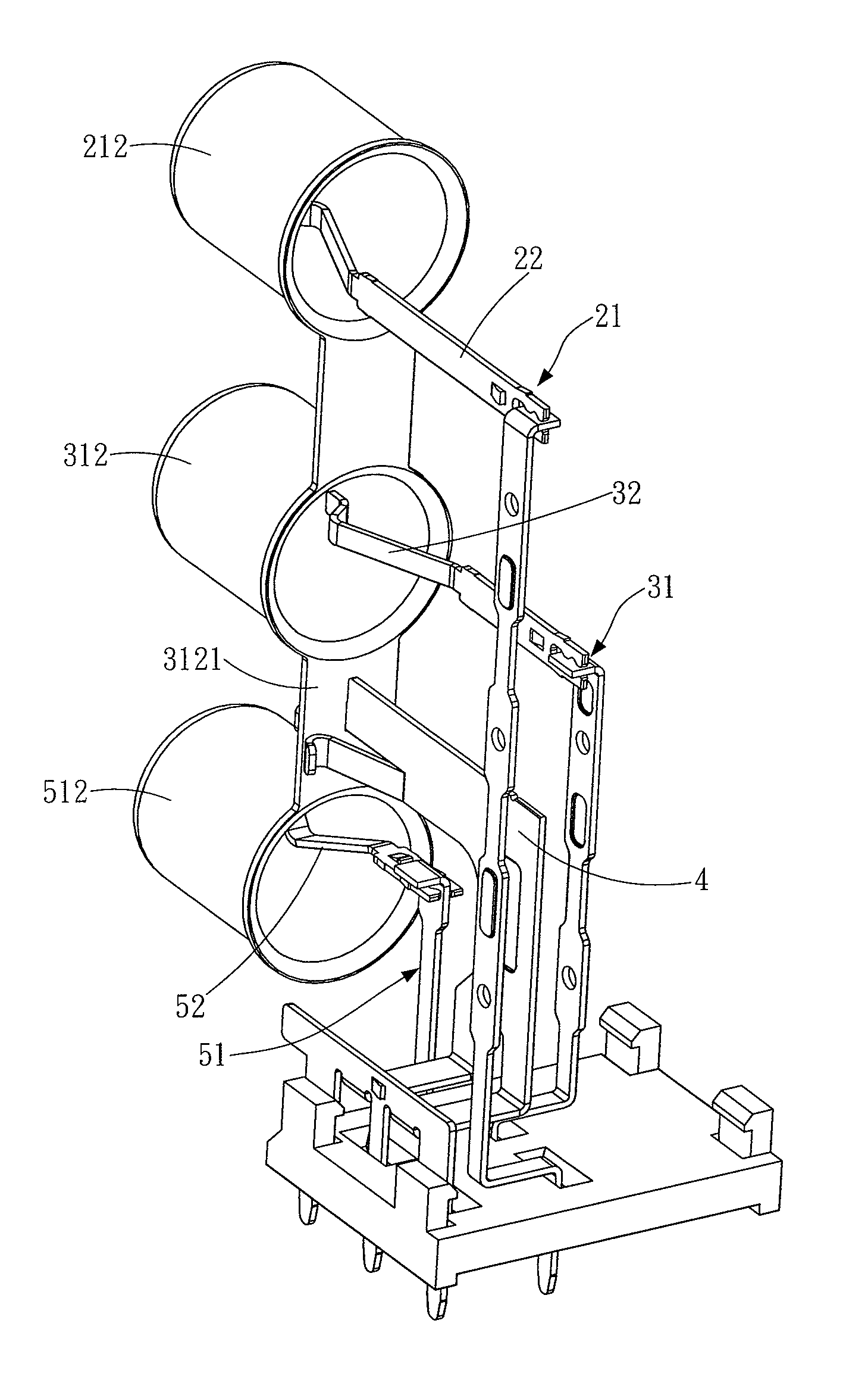
[0044]Please refer to FIG. 13, which illustrates the position distributions of the terminals according to the In the present embodiment, a triangle area 6 surrounded by the first signal terminal 22, the second signal terminal 32 and the third signal terminal 52. The ground terminal 4 is located in the triangle area 6 such that a signal flow space is formed between the ground terminal 4 and respectively the first signal terminal 22, the second signal terminal 32, and the third signal terminal 52. In other words, the first signal flow space 61 formed between the ground terminal 4 and first signal terminal 22 is used as a signal flow path for the first signal terminal 22. The second signal flow space 62 formed between the ground terminal 4 and the second signal terminal 32 is used as a signal flow path for the second signal terminal 32. The third signal flow space 63 formed between the ground terminal 4 and the third signal terminal 52 is used as a signal flow path for the third signa...

third embodiment

[0047]In the descriptions mentioned above, the third embodiment disposes the second ground terminal 42 between the first signal terminal 22 and the second signal terminal 32 as an example, which should not be considered as a general limitation to the disclosure. According to the alignments of each signal terminal and each ground terminal, the first ground terminal 41 may be aligned between the first signal terminal 22 and the second signal terminal 32, or alternatively both the first ground terminal 41 and the second ground terminal 42 are aligned between the first signal terminal 22 and the second signal terminal 32.

[0048]Please refer to FIGS. 19, 20 and 21 for a fourth embodiment according to the disclosure. FIG. 19 is an explosion view of an electrical connector; FIG. 20 is a partial perspective view of the electrical connector; and FIG. 21 is a top partial perspective view of the electrical connector. The differences between the present embodiment and the third embodiment are th...

fourth embodiment

[0052]In the previous descriptions, the fourth embodiment dispose the second ground terminal 42 between the first signal terminal 22, the second signal terminal 32 and the third signal terminal 52, which should not be considered as a general limitation to the whole disclosure. In accordance with the alignments of each signal terminal and each ground terminal, the first ground terminal 41 or the third ground terminal 43 is selectively aligned in the triangle area 6; or alternatively more than two ground terminals may be aligned in the triangle area 6. Additionally, the triangle area is only an example for the area surrounded by the signal terminals, which should not be considered as a general limitation to the whole disclosure.

[0053]A preferred application for the embodiments is an RCA connector. The advantage for the electrical connector according to the embodiments of the disclosure is to dispose a ground terminal between different signal terminals. The ground terminal may be integ...


PUM


Abstract

An electrical connector for reducing high frequency crosstalk interferences is provided to insert with at least two mating elements. The electrical connector includes a first joint, a first signal terminal, a second joint, a second signal terminal and a ground terminal. The first joint and second joint are respectively used to be inserted by the mating elements. The first signal terminal is electrically connected with the mating element inserted within the first joint. The second signal terminal is electrically connected with the mating element inserted within the second joint. The ground terminal is electrically connected with the first joint and the second joint, and disposed between the first signal terminal and the second signal terminal. Signal flow spaces located between the ground terminal and respectively the first signal terminal and second signal terminals are used as signal flow paths for the first signal terminal and second signal terminal respectively.

Description

CROSS-REFERENCES TO RELATED APPLICATIONS[0001]This non-provisional application claims priority under 35 U.S.C. §119(a) on Patent Application No. 101109394 filed in Taiwan, R.O.C. on Mar. 19, 2012, the entire contents of which are hereby incorporated by reference.BACKGROUND[0002]1. Technical Field[0003]The disclosure relates to an electrical connector, and more particularly to an electrical connector for reducing high frequency crosstalk interferences.[0004]2. Related Art[0005]Nowadays, various electrical devices such as a television, recorder, video player, CD player, DVD (Digital Video Disc) player etc., are all equipped with plugin connectors to connect with each other for signal transmission.[0006]Generally a connector has multiple signal terminals. When signals are sent through the signal terminals, voltage noise interferences are generated due to electromagnetic coupling between adjacent signal terminals; which is the electromagnetic field interference effect generated within t...

Claims


Application Information

Patent Timeline
Patent Type & Authority Patents(United States)
IPC IPC(8): H01R13/6585H01R13/648
CPCH01R24/50H01R13/6467H01R13/659H01R13/6585
Inventor LI, LI-CHENHSIAO, YI-HUI
Owner CONCRAFT HLDG
Why Eureka
Try Eureka