Double guiding rod pushing type rotary grooving machine

A double-guide, push-type technology, which is applied in the field of pipe fitting end processing, can solve the problems that the hydraulic mechanism cannot meet the size requirements, the force of the mechanism is unbalanced, and the mechanism is prone to vibration, etc., and achieve high push transmission efficiency and deep dimension Accurate and improve work efficiency

Pending Publication Date: 2019-03-01
苏州华尔普机械有限公司
View PDF1 Cites 0 Cited by
  • Summary
  • Abstract
  • Description
  • Claims
  • Application Information

AI Technical Summary

Problems solved by technology

The original mechanism of our company is driven by a hydraulic cylinder, and it is based on the principle of a lever fulcrum; the patent number in the prior art is 201820357171.3, which discloses a chip-free forming device for pipe fittings, a flat chamfering machine for pipe ends, and a chip-free rotary cutting head. The propulsion mechanism is also driven by an offset cylinder. Due to the offset installation of the propulsion drive parts, the force on the mechanism will be unbalanced, and the mechanism is prone to vibration when rotating, and the hydraulic mechanism is currently unable to meet the increasingly stringent size requirements of some products. , the positioning is not accurate enough, the transmission efficiency is low, etc.

Method used


Image

  • Double guiding rod pushing type rotary grooving machine
  • Double guiding rod pushing type rotary grooving machine
  • Double guiding rod pushing type rotary grooving machine

Examples


Embodiment

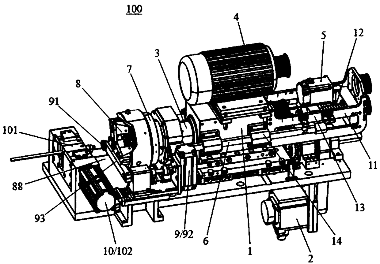
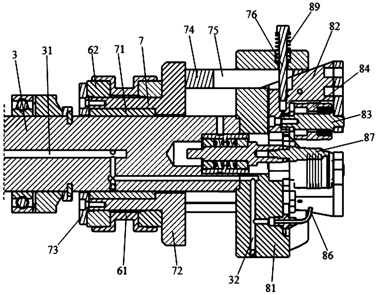
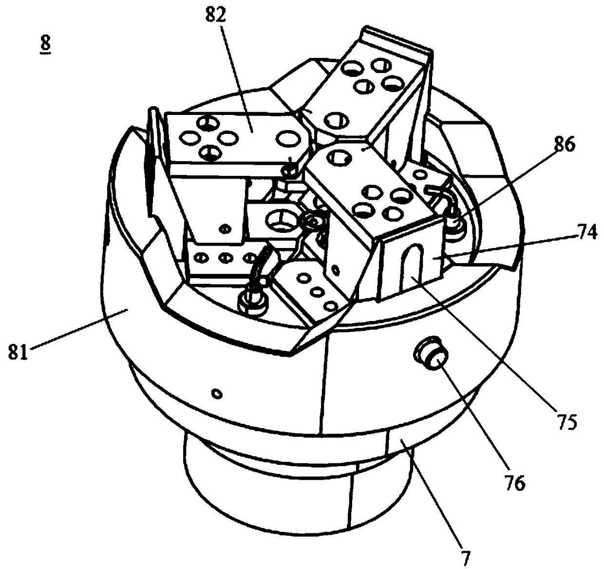
[0024] Please refer to Figure 1-Figure 4 , the present embodiment is a double-guide push-type slotting machine 100, which includes a main shaft rotation support base 1, a first driving member 2 for driving the main shaft rotation support base 1 to move left and right, a main shaft 3 arranged on the main shaft rotation support base 1, The second drive member 4 that drives the main shaft 3 to rotate, the third drive member 5 fixed on the main shaft rotation support base 1, the double drive parts that are driven by the third drive member 5 to move left and right and symmetrically distributed on both sides of the main shaft rotation support base 1 The guide rod 6, driven by the double guide rods 6, moves axially relative to the main shaft 3 and rotates synchronously with the main shaft 3. The rotating propulsion ring 7 is arranged at the end of the main shaft 3 and is driven by the rotating propulsion ring 7 to move closer to the axis center of the main shaft 3. A rotary groove t...


PUM


Abstract

The invention discloses a double-guiding-rod pushing type rotary grooving machine. The double-guiding-rod pushing type rotary grooving machine comprises a spindle rotating supporting seat, a first driving part, a main shaft, a second driving part, a third driving part, double guiding rods, a rotating pushing ring, and a rotary grooving cutter rest chuck system, wherein the first driving part drives the main shaft rotating supporting seat to move left and right; the main shaft is arranged on the main shaft rotating supporting seat; the second driving part drives the main shaft to rotate; the third driving part is fixed on the main shaft rotating supporting seat; the double guiding rods are driven by the third driving part to move left and right and are symmetrically arranged on two sides ofthe main shaft rotating supporting seat; the rotating pushing ring is driven by the double guiding rods to do axial motion relative to the main shaft and rotates synchronous with the main shaft; andthe rotary grooving cutter rest chuck system is arranged on the end portion of the main shaft, and is driven by the rotating pushing ring to draw close to an axis of the main shaft, so that the rotarycutting is achieved. According to the double guiding rod pushing type rotary grooving machine, the front end roller cutter working section is effectively controlled, the power transmitting is more direct and effective, the positioning is more accurate, and the working efficiency is higher.

Description

【Technical field】 [0001] The invention belongs to the technical field of pipe fitting end processing, and in particular relates to a double-guide-rod push-type grooving machine. 【Background technique】 [0002] No matter what kind of chuck structure or processing method is required when the slotting machine is processed, other independent driving mechanisms are required. The original mechanism of our company is driven by a hydraulic cylinder, and it is based on the principle of a lever fulcrum; the patent number in the prior art is 201820357171.3, which discloses a chip-free forming device for pipe fittings, a flat chamfering machine for pipe ends, and a chip-free rotary cutting head. The propulsion mechanism is also driven by an offset cylinder. Due to the offset installation of the propulsion drive parts, the force on the mechanism will be unbalanced, and the mechanism is prone to vibration when rotating, and the hydraulic mechanism is currently unable to meet the increasin...

Claims


Application Information

Patent Timeline
Patent Type & Authority Applications(China)
IPC IPC(8): B21D22/14
CPCB21D22/14
Inventor 马翔袁良勇
Owner 苏州华尔普机械有限公司
Why Eureka
Try Eureka