
Carrying device

A technology of a carrying device and a clamping arm, which is used in transportation and packaging, bicycle accessories, panniers on bicycles, etc., can solve problems such as inconvenience, separation of the clamping arm unit of the basket frame assembly, separation of bolts and nuts, etc.

Active Publication Date: 2019-03-01
RUIZHEN BICYCLE COMPONENT TAICANG
View PDF8 Cites 0 Cited by
  • Summary
  • Abstract
  • Description
  • Claims
  • Application Information

AI Technical Summary

Problems solved by technology

[0005] Install the carrying device behind the handlebar of the bicycle and against the handlebar standpipe of the bicycle. When it is necessary to adjust the angle of the basket assembly seat, it is necessary to unscrew each bolt in a direction away from the second adjustment piece, so that the original The first ring teeth and the second ring teeth that are engaged to prevent the basket assembly seat and the clamp arm units from rotating each other can adjust the angle of the basket assembly seat. However, due to The length of the meshing parts of the ring teeth is too long, and each bolt must be unscrewed in a large amount away from the second adjustment member. At this time, the corresponding bolts and nuts are easily separated, and the basket assembly seat is formed. It is really inconvenient to disengage from the clamp arm units

Method used


Image

  • Carrying device
  • Carrying device
  • Carrying device

Examples


Embodiment Construction

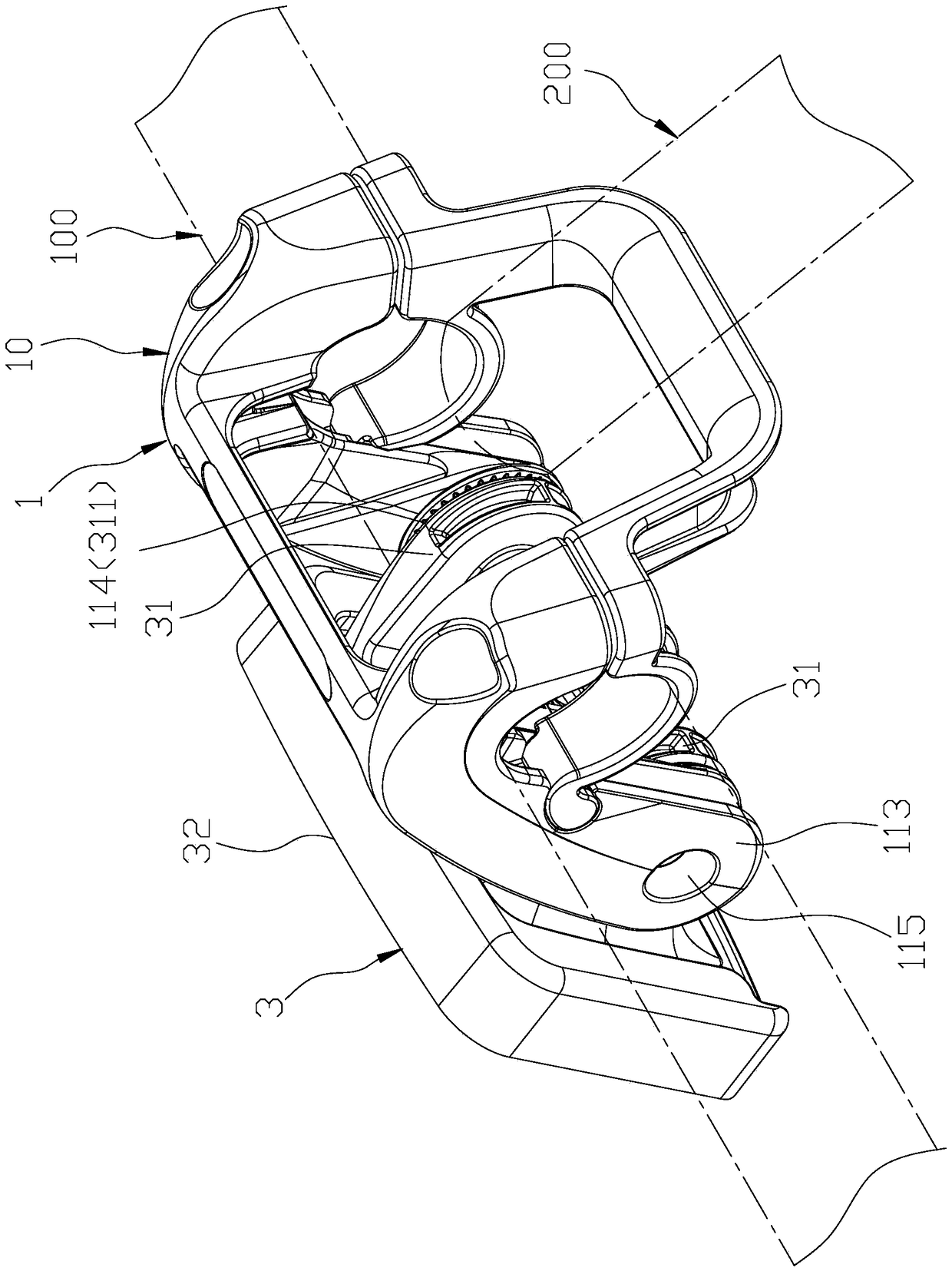
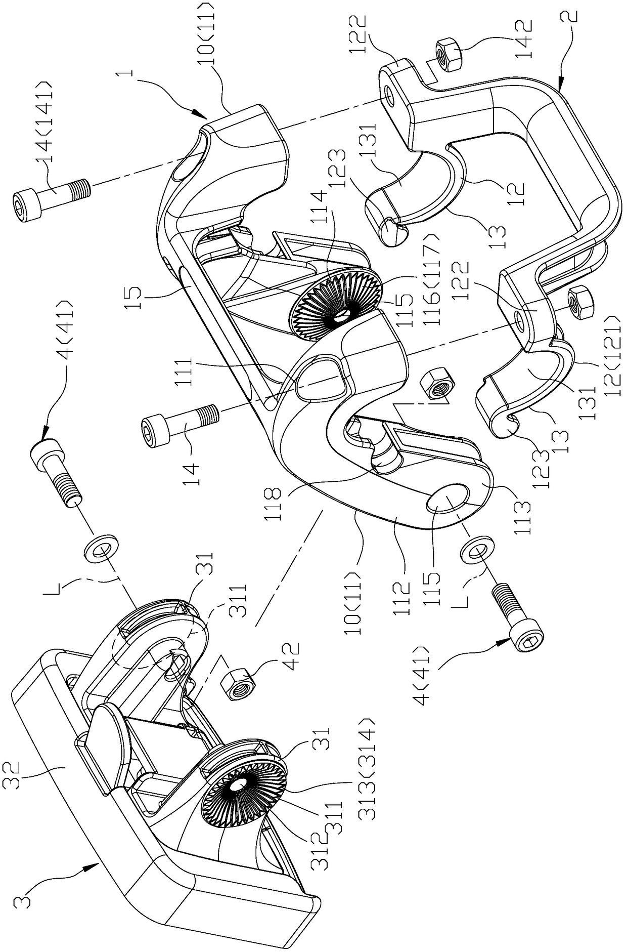
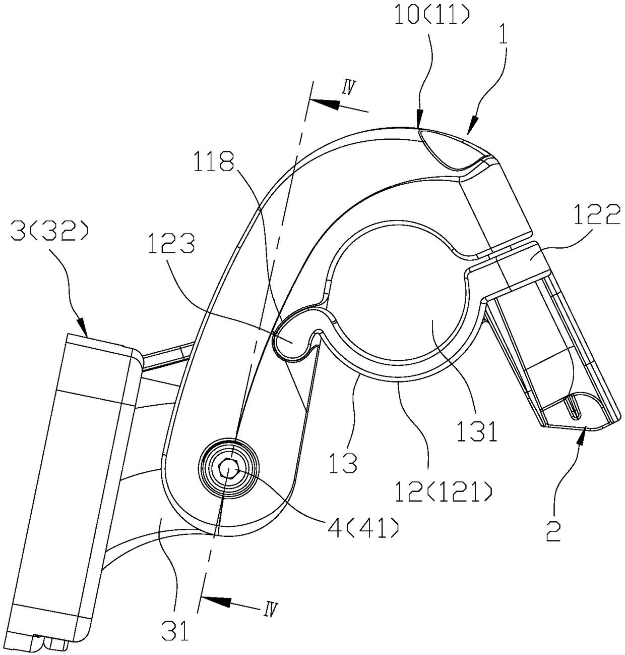
[0022] refer to figure 1 and figure 2 , an embodiment of the carrying device of the present invention is suitable for being installed at the junction of a bicycle handle 100 and a handle riser 200, and the carrying device includes a clamp arm unit 1, an abutting member 2, and a basket assembly seat 3 , and a connection unit 4 .

[0023] The clamp arm unit 1 includes two clamp arms 10 arranged at intervals, two locking members 14, and a connecting member 15 connected between the clamp arms 10, each clamp arm 10 has a fixed arm member 11, and a movable The fastening part 12 is detachably connected to the fixing arm part 11 . The fixing arm parts 11 are integrally formed with the connecting part 15 .

[0024] Each fixed arm 11 has an upper arc block 111, an arm portion 112 extending forward and downward from the upper arc block 111, a first connection connected to the arm portion 112 and opposite to one end of the upper arc block 111 part 113, and a pivot hole 118 disposed o...


PUM


Abstract

The invention relates to a carrying device comprising a clamping arm unit, a basket assembly and a connecting unit. The clamping arm unit includes two clamping arms, each clamping arm has a first pivoting area and a first axial hole; the first pivoting area has a first spherical surface and multiple first teeth part which are convexly disposed on the first spherical surface and radially surround around a first shaft hole; a basket rack grouping seat comprises two connection lugs and a grouping board; each connection lug is equipped with a second pivoting area and a second shaft hole, wherein the second pivoting area and the second shaft hole are matched in a convex and concave manner by corresponding to a first pivoting area. The second pivoting area is equipped with a second spherical surface and multiple second teeth part which are convexly arranged on the second spherical surface and radially surround the outer periphery of the second shaft hole. The connection area is arranged in first and second shaft holes in a penetrating manner and used for engaged the first tooth part and with the second tooth part. Therefore, the connection lugs are fixed at clamp arms in a rotation-stopping manner.

Description

【Technical field】 [0001] The invention relates to a vehicle accessory, in particular to a bearing device installed on a vehicle frame. 【Background technique】 [0002] The bicycle supporting device proposed in patent cases such as prior technical documents TW M364644 and TW M267143 is installed on the handlebar of the bicycle and is used to install the bicycle basket frame, including a clamp arm unit and an abutting unit connected to the clamp arm unit, and a basket assembly seat connected to one end of the clamping arm unit opposite to the abutting unit, wherein the clamping arm unit includes two clamping parts arranged at intervals and respectively having a set of holes, and a connecting clamping part and the clamping part The connecting part between the basket assembly seat, the abutting unit connects the buckle parts, when in use, the sleeve holes are set on the handlebar of the bicycle, the abutting unit is pushed against the handle standpipe of the bicycle, and finally ...

Claims


Application Information

Patent Timeline
IPC IPC(8): B62J9/00
CPCB62J9/21
Inventor 许国忠
Owner RUIZHEN BICYCLE COMPONENT TAICANG
Learn More