
A method and device for processing delay jitter

A technology for processing delay and processing rate, applied in the field of optical communication, it can solve the problems of customer signal transmission damage, system reliability and performance impact, inability to meet reliability requirements, etc., so as to reduce delay jitter and improve data transmission quality. Effect

Active Publication Date: 2020-09-29
SANECHIPS TECH CO LTD
View PDF5 Cites 0 Cited by
  • Summary
  • Abstract
  • Description
  • Claims
  • Application Information

AI Technical Summary

Problems solved by technology

In the optical transport network (OTN) system, the delay jitter in the transmission link and the reception link will cause transmission damage to customer signals, which will affect the reliability and performance of the entire system. The current mainstream DSP chips in the industry have no special issues. processing
In 100G / 400G services, 100G / 400G pass-through services and 100G / 400G loopback services, the reliability and performance of the system will be affected, and services with special requirements for delay requirements, such as 100G / 400G services, will not be able to meet Reliability requirements affect the application of 100G / 400G DSP chips in the market

Method used


Image

  • A method and device for processing delay jitter
  • A method and device for processing delay jitter
  • A method and device for processing delay jitter

Examples


Embodiment Construction

[0071] In order to make the purpose, technical solution and advantages of the present invention more clear, the embodiments of the present invention will be described in detail below in conjunction with the accompanying drawings. It should be noted that, in the case of no conflict, the embodiments in the present application and the features in the embodiments can be combined arbitrarily with each other.

[0072] The steps shown in the flowcharts of the figures may be performed in a computer system, such as a set of computer-executable instructions. Also, although a logical order is shown in the flowcharts, in some cases the steps shown or described may be performed in an order different from that shown or described herein.

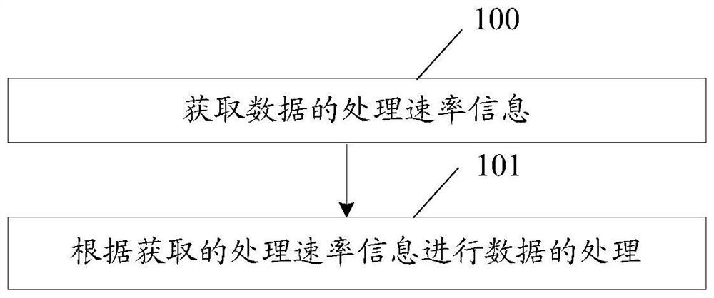
[0073] figure 1 It is a flowchart of a method for processing delay jitter according to an embodiment of the present invention, such as figure 1 shown, including:

[0074] Step 100, acquiring data processing rate information;

[0075] Optionally, the pr...


PUM


Abstract

The invention discloses a method and device for processing a delay jitter. The method comprises the following steps: acquiring data processing rate information; and processing data according to the acquired processing rate information. The embodiment of the invention reduces the delay jitter and improves the data transmission quality.

Description

technical field [0001] This article involves but is not limited to optical communication technology, especially a method and device for dealing with delay jitter. Background technique [0002] In the development of transmission technology, optical fiber is an indispensable medium. For how to use the least amount of optical fiber to transmit the most abundant information, the development of optical transmission has gone through the following stages: Space Division Multiplexing (SDM), Time Division Multiplexing (TDM) and Wavelength Division Multiplexing (WDM) . [0003] At present, wired transmission is still dominated by wavelength division multiplexing; commercial wavelength division transmission has gradually evolved from 40 gigabits (G) to 100G and 400G. In addition, the data transmission distance is constantly expanding; the rapid growth of data services also puts forward higher requirements for the transmission network: large capacity, low cost, fast and flexible servi...

Claims


Application Information

Patent Timeline
Patent Type & Authority Patents(China)
IPC IPC(8): H04J14/02H04L12/26
CPCH04J14/0227H04L43/0888
Inventor 芦秋雁苏胜涛贾世英
Owner SANECHIPS TECH CO LTD
Learn More