
Claw pole type motor

A technology of motors and claw poles, which is applied to electric components, synchronous motors with stationary armatures and rotating magnets, synchronous machines, etc., can solve the problems of increasing the manufacturing cost of motors, and achieve the effect of reducing manufacturing costs

Inactive Publication Date: 2019-03-01
PIERBURG PUMP TECH
View PDF12 Cites 0 Cited by
  • Summary
  • Abstract
  • Description
  • Claims
  • Application Information

AI Technical Summary

Problems solved by technology

This fact increases the manufacturing cost of the motor

Method used


Image

  • Claw pole type motor
  • Claw pole type motor

Examples


Embodiment Construction

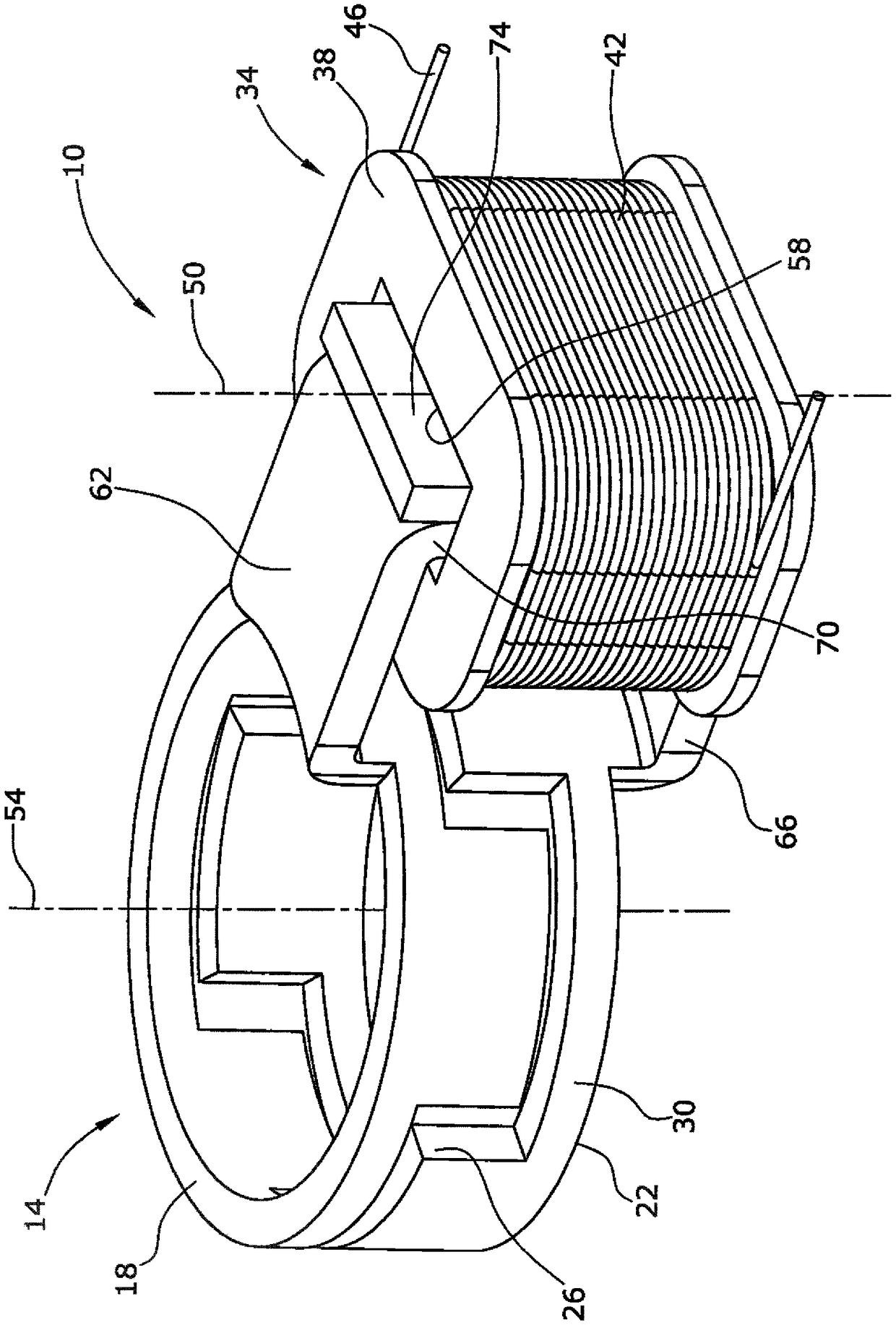
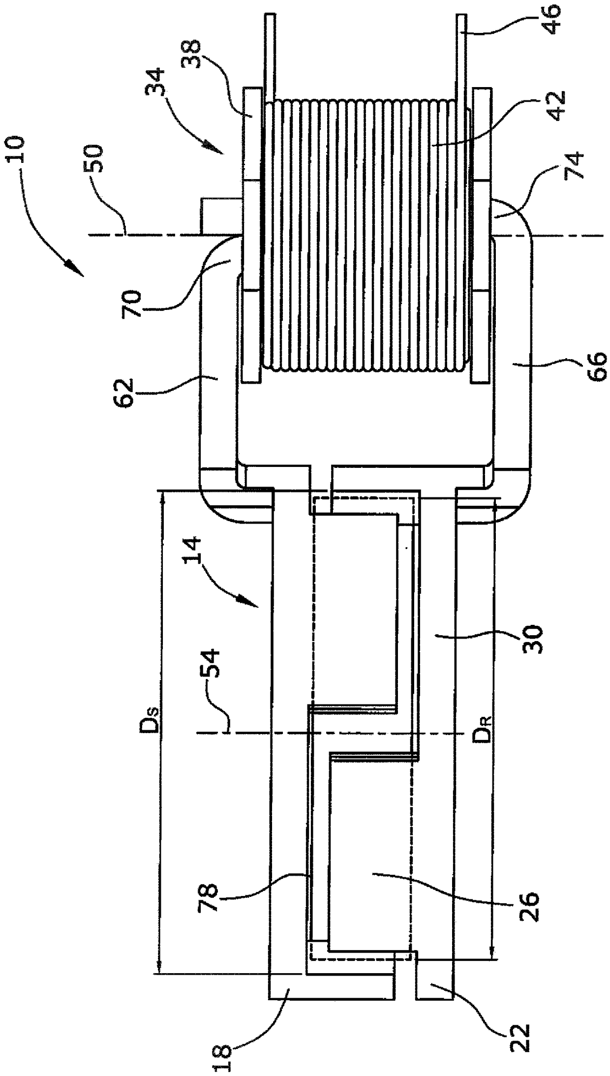
[0022] figure 1 Shown is a perspective view of an automotive single-phase electric motor 10 of the claw pole type (without a motor rotor) comprising a stator 14 defined by two annular stator bodies 18, 22 made of ferromagnetic stamped Made of bent sheet metal parts. Each body 18 , 22 is provided with three magnetic rectangular-shaped claws 26 which engage with the same number of claws 26 of the other body 18 , 22 . The claws 26 of rectangular shape are connected by a back iron ring 30 . The back iron ring 30 and claw 26 of each stator body 18, 22 are arranged on a single cylindrical face of an imaginary cylinder.

[0023] The electric motor 10 also includes a stator coil arrangement 34 for magnetizing the stator bodies 18 , 22 . The stator coil device 34 is arranged as a satellite with respect to the stator 14 , that is, the stator coil device 34 is arranged at a certain radial distance from the stator 14 . The stator coil arrangement 34 is defined by a cuboidal coil 38 co...


PUM


Abstract

The present inventions refers to an automotive single-phase electrical motor (10) of the claw pole type comprising a motor rotor (78) rotating around a rotating axis (54), a stator (14) defined by a mating pair of annular stator bodies (18, 22), each body (18, 22) being provided with at least two magnetic claws (26) meshing with the claws (26) of the other body (18, 22), and a stator coil arrangement (34) for magnetizing the stator bodies (18, 22). The stator coil arrangement (34) Is provided as a satellite and radial arms (62, 66) of the stator bodies (18, 22) are magnetically connected to each other at the stator coil arrangement (34).

Description

technical field [0001] The invention relates to a claw-pole type automobile single-phase motor. [0002] In particular, the present invention relates to an automotive single-phase motor for driving accessory parts or devices of an automobile. These components or devices may be eg auxiliary units, actuators or pumps. Therefore, the automotive electric motor according to the present invention is not an automotive engine for driving a vehicle. An automotive electric motor includes a motor rotor rotating about an axis of rotation and a stator defined by mating annular stator bodies. Each body is provided with at least two pole claws that engage with claws of the other body. The electric motor also includes a stator coil arrangement for magnetizing the stator body. Background technique [0003] A claw pole motor of this type is known from prior art US 2007 / 0278894 A1. A claw pole type motor includes a motor rotor rotatably disposed in a motor stator. The stator is defined b...

Claims


Application Information

Patent Timeline
Patent Type & Authority Applications(China)
IPC IPC(8): H02K21/14H02K1/14
CPCH02K1/145H02K21/14H02K21/125H02K2201/12
Inventor E.林德纳M.齐尔T.亨克
Owner PIERBURG PUMP TECH
Learn More