Connection lock catch

A connection lock and rotary connection technology, applied in the direction of connection components, instruments, identification devices, etc., can solve problems such as low disassembly and assembly efficiency

Active Publication Date: 2019-06-11
SHENZHEN AOTO ELECTRONICS
View PDF20 Cites 2 Cited by
  • Summary
  • Abstract
  • Description
  • Claims
  • Application Information

AI Technical Summary

Problems solved by technology

[0003] Based on this, it is necessary to provide a connection lock to solve the probl...

Method used


Image

  • Connection lock catch
  • Connection lock catch
  • Connection lock catch

Examples


Embodiment Construction

[0031] In order to facilitate the understanding of the present invention, the present invention will be described more fully below with reference to the associated drawings. Preferred embodiments of the invention are shown in the accompanying drawings. However, the present invention can be embodied in many different forms and is not limited to the embodiments described herein. On the contrary, the purpose of providing these embodiments is to make the disclosure of the present invention more thorough and comprehensive.

[0032] It should be noted that when an element is referred to as being “fixed” to another element, it can be directly on the other element or there can also be an intervening element. When an element is referred to as being "connected to" another element, it can be directly connected to the other element or intervening elements may also be present. The terms "vertical," "horizontal," "left," "right," and similar expressions are used herein for purposes of ill...


PUM


Abstract

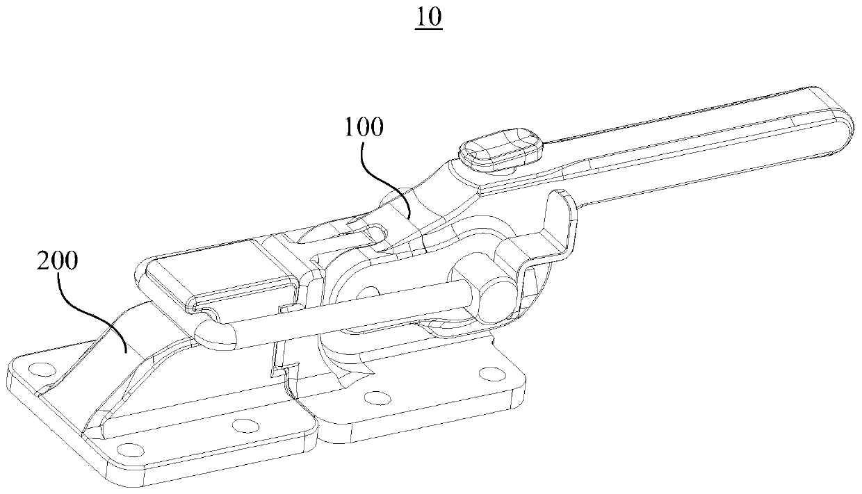
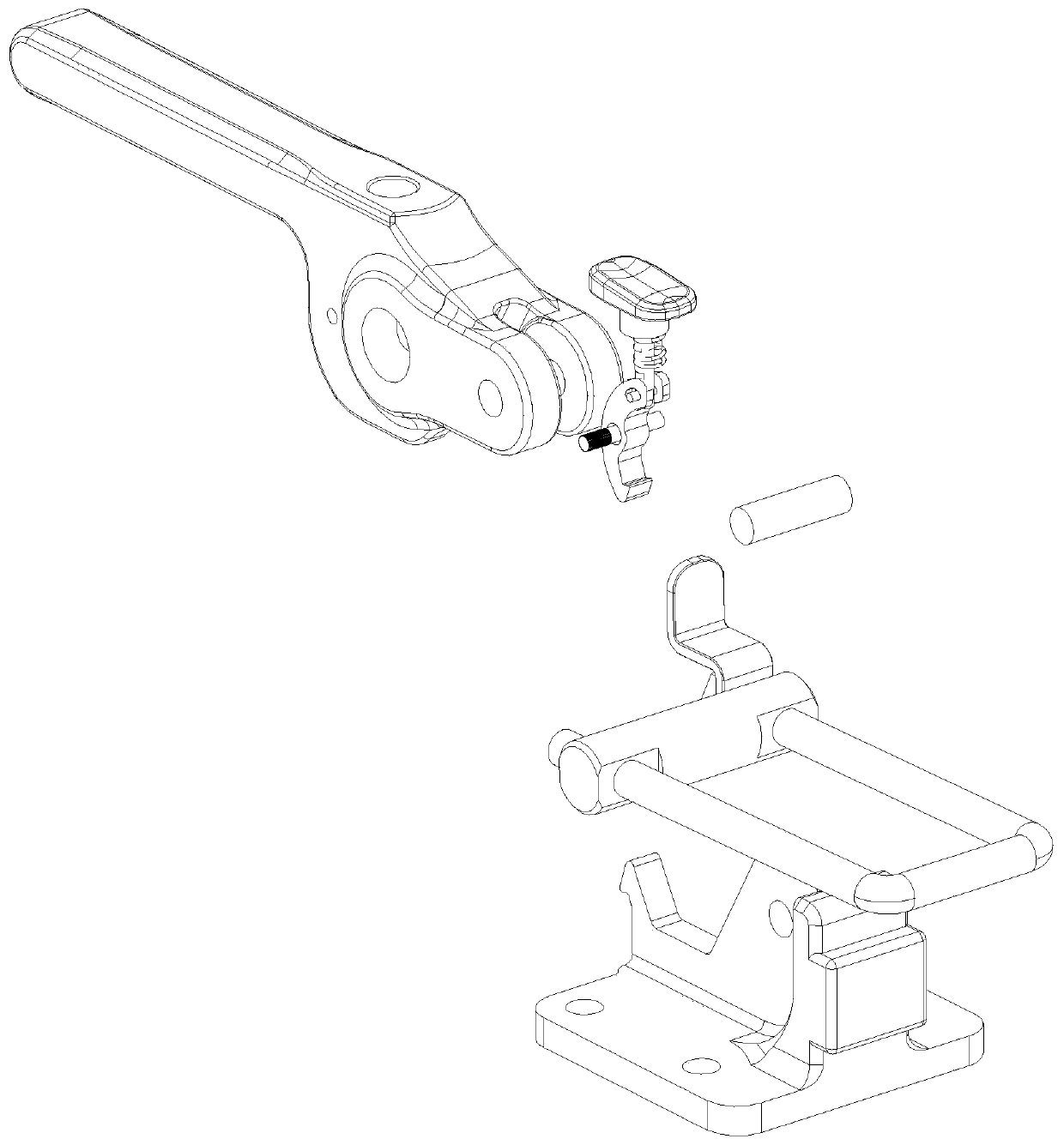
The invention relates to a connection lock catch. The connection lock catch includes a first connection block and a second connection lock, wherein the first connection lock is detachably fixed with the second connection lock. The first connection lock includes a base, a handle, a hanging hook, a clamping hook and an unlocking assembly, wherein a buckle site is formed on the base, the handle is rotatably connected with the base, the hanging hook is fixed on the handle and fixedly clamped with the second connection lock, the clamping lock is arranged on the handle and rotatably connected with the handle, the clamping hook is clamped at the buckle site in a natural state, and the unlocking assembly is in drive connection with the clamping hook, when external force acts on the unlocking assembly, and the clamping hook rotates relative to the handle and is disengaged from the buckle site in the rotation process. Through the linkage of the unlocking assembly and the clamping hook, the unlocking assembly can move relative to the clamping hook only by pressing the unlocking assembly, the clamping hook is pushed to rotate, the clamping hook is disengaged from the buckle site in the rotation process, one-key unlocking is achieved, the operation of the connection lock catch is greatly simplified, and the convenience of operation is improved.

Description

technical field [0001] The invention relates to the field of LED display screens, in particular to a connection lock. Background technique [0002] At present, the splicing between LED display units is generally connected and locked by a high-strength locking device. The traditional locking device generally includes metal fixing pieces and screws, and the two ends of the metal pieces are respectively fixed on the corresponding side by screws. On the adjacent LED display unit, so as to achieve the purpose of fixed connection, but the connection method of this LED display unit is time-consuming and laborious in the actual splicing / unsplicing process, and the efficiency is low. There are also buckles that are fixed to each other. However, the traditional buckle operation is more troublesome. When two LED display units are spliced, it is often necessary to manually adjust the position of the LED display unit and then fix it. Generally, multiple people are required to operate and...

Claims


Application Information

Patent Timeline
IPC IPC(8): G09F9/33F16B2/10
Inventor 肖华勇何昆鹏吴振志吴涵渠
Owner SHENZHEN AOTO ELECTRONICS
Why Eureka
Try Eureka