Eureka AIR delivers breakthrough ideas for toughest innovation challenges, trusted by R&D personnel around the world.

Lifting storage kitchen rack

A technology of lifting limit and components, applied in the field of kitchen storage, can solve problems such as complex structure, easy metal friction sound, and inconvenient for children

Pending Publication Date: 2019-03-08
杭州凯畅五金制品有限公司
View PDF2 Cites 5 Cited by
  • Summary
  • Abstract
  • Description
  • Claims
  • Application Information

AI Technical Summary

Problems solved by technology

However, it also brings the problem of inconvenient access, because the wall-mounted kitchen cabinet has a certain height from the ground, and the articles in the access cabinet, especially the articles placed on the upper floor, must be stored on a stool or a ladder. It is very inconvenient for housewives, the elderly and children; and based on the above reasons, the wall cabinets in many families currently only have one layer of storage tables, and their space utilization is actually very effective.
The Chinese utility model patent No. ZL200420082765.6 discloses an electric lifting wall-mounted kitchen cabinet, which is composed of motor, sprocket, transmission chain, connecting rod, pulley and other structures; the Chinese utility model patent No. ZL200420090774.X The patent discloses another screw-type electric lifting kitchen cabinet, which is composed of a motor, a lifting screw and other structures. The lifting kitchen cabinets using the above two schemes can solve the problem of picking things from high altitudes, but the structure is relatively complicated. The cost is high, and the mechanical structure is used to drive the lifting, which is easy to generate metal friction sound, and the track set on the wall is extremely unsightly

Method used


Image

  • Lifting storage kitchen rack
  • Lifting storage kitchen rack
  • Lifting storage kitchen rack

Examples


Embodiment Construction

[0017] The following will clearly and completely describe the technical solutions in the embodiments of the present invention with reference to the accompanying drawings in the embodiments of the present invention. Obviously, the described embodiments are only some, not all, embodiments of the present invention.

[0018] In describing the present invention, it should be understood that the terms "upper", "lower", "front", "rear", "left", "right", "top", "bottom", "inner", " The orientation or positional relationship indicated by "outside", etc. is based on the orientation or positional relationship shown in the drawings, and is only for the convenience of describing the present invention and simplifying the description, rather than indicating or implying that the referred device or element must have a specific orientation, so as to Specific orientation configurations and operations, therefore, are not to be construed as limitations on the invention.

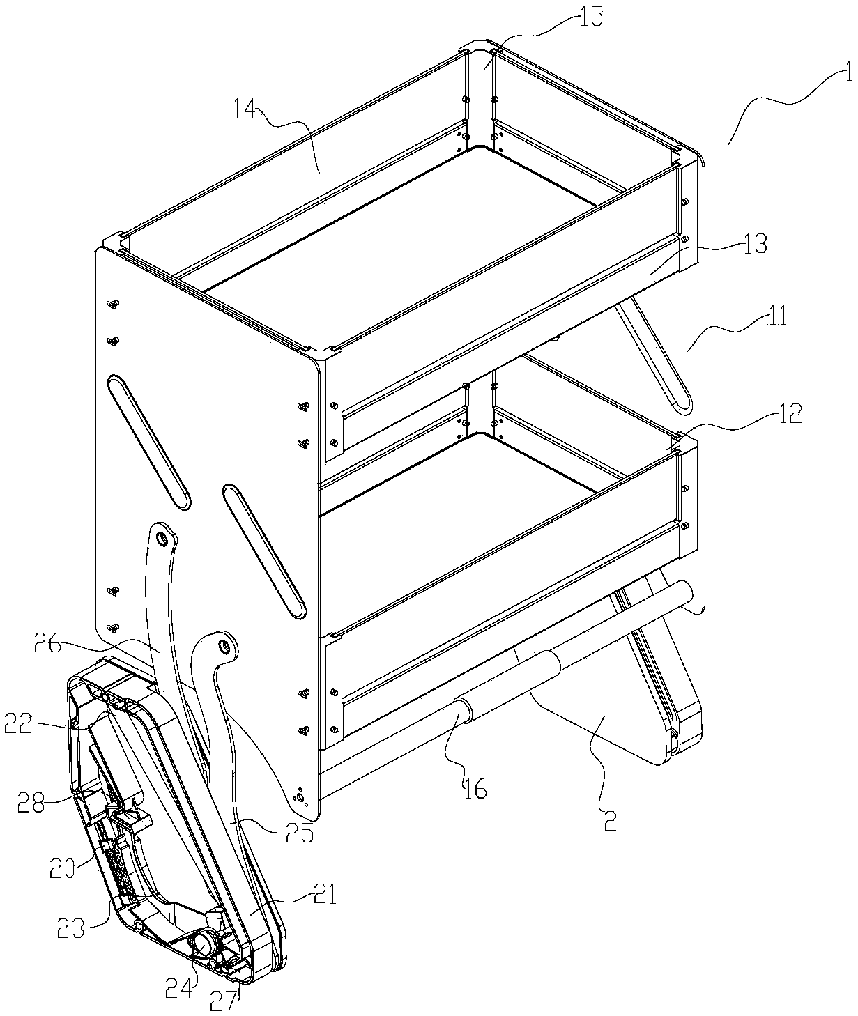
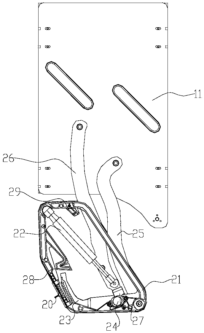
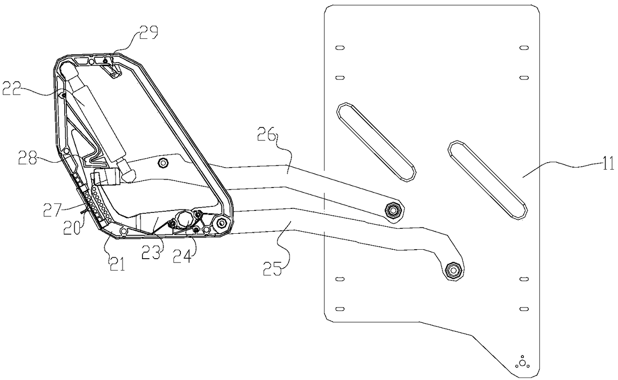
[0019] Such as Figure 1...


PUM


Abstract

The invention relates to the field of storage of kitchen, and provides a lifting storage kitchen rack. The lifting storage kitchen rack comprises a lifting limiting assembly and a cabinet basket, wherein the lifting limiting assembly is mounted on the inner side wall of a cabinet; and the cabinet basket is connected to the movable end of the lifting limiting assembly. The lifting storage kitchen rack is characterized in that a push-and-pull component which is used for applying force for holding the cabinet basket with hands is arranged on the cabinet basket; the lifting limiting assembly comprises a first oscillating arm and a second oscillating arm, and far end portions of the first oscillating arm and the second oscillating arm are separately hinged to side walls of the cabinet basket; anear end portion of the first oscillating arm is hinged to the inside of the lifting limiting assembly; a near end portion of the second oscillating arm can move in the lifting limiting assembly along a certain curve path; and the second oscillating arm can be positioned at the two ends of the curve path. According to the lifting storage rack, an oscillating mode replaces a vertical lifting mode,the lifting structure is simplified, the cost is reduced, and articles are stored quite conveniently. Moreover, the near end portion of the second oscillating arm is positioned by the curve path, thecabinet basket can be maintained in an aligned state in a lifting process, and dumping of the articles can be avoided.

Description

technical field [0001] The invention relates to the field of kitchen storage, in particular to a lifting and storage kitchen shelf. Background technique [0002] With the continuous improvement of people's living standards and the improvement of housing conditions, family kitchens and their utensils have also undergone fundamental changes, and various modern kitchen utensils have entered the kitchens of thousands of households. Therefore, how to maximize the use of kitchen space in order to accommodate various kitchen items has always been a problem that the kitchen and bathroom industry has been working on. Existing cabinets are generally divided into several types such as base cabinets, wall cabinets, and high cabinets. As far as wall cabinets are concerned, the limited space of the kitchen is fully utilized, and the storage space of the kitchen is greatly improved. When in use, store some infrequently used items and utensils in the wall-mounted kitchen cabinet, which can...

Claims


Application Information

Patent Timeline
IPC IPC(8): A47B77/14A47B77/00A47B45/00A47B96/00A47J47/16
CPCA47B45/00A47B77/00A47B77/14A47B96/00A47J47/16
Inventor 车毛毛
Owner 杭州凯畅五金制品有限公司
Why Eureka
Eureka Blog
Learn More