Vomit collecting equipment for medical patient

A technology for collecting equipment and vomit, which is applied in the direction of utensils receiving saliva, etc., and can solve problems such as inconvenient vomiting for patients

Inactive Publication Date: 2019-03-08
张学云
View PDF9 Cites 1 Cited by
  • Summary
  • Abstract
  • Description
  • Claims
  • Application Information

AI Technical Summary

Problems solved by technology

[0003] In order to overcome the disadvantages that ordinary trash cans are inconvenient for patients to vomit and the smell of vomit will float out, the technical problem of the present invention is to provide a vomit collection device for medical patients that is convenient for patients to vomit and does not spread the smell of vomit

Method used


Image

  • Vomit collecting equipment for medical patient
  • Vomit collecting equipment for medical patient
  • Vomit collecting equipment for medical patient

Examples


Embodiment 1

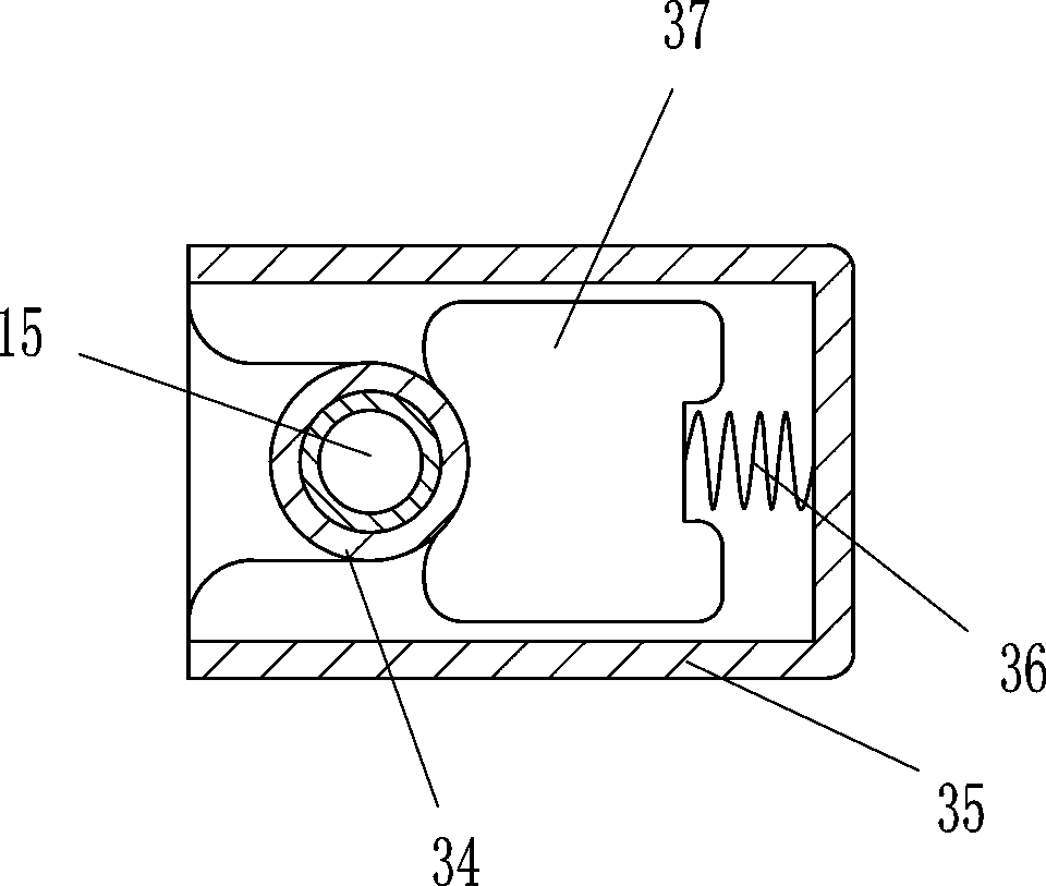
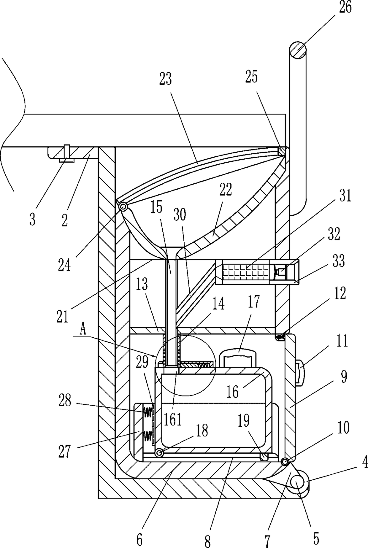
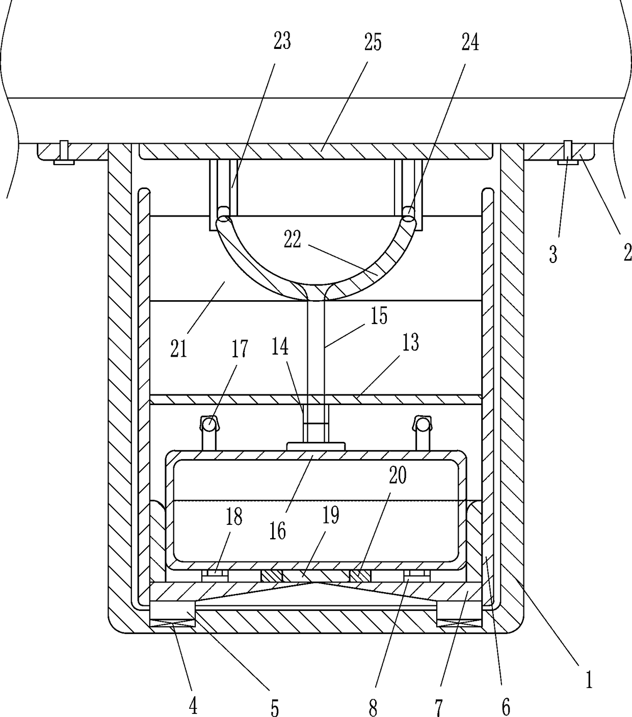
[0020] A device for collecting vomitus from medical patients, such as Figure 1-4 As shown, it includes an outer box body 1, a fixed plate 2, a screw 3, a bearing seat 4, a rotating shaft 5, an inner box body 6, a triangular connection block 7, a slideway 8, a cover plate 9, a hinge 10, a handle 11, an elastic Buckle 12, fixed partition 13, fixed sleeve 14, hard conduit 15, container box 16, handle 17, roller 18, block 19, bar-shaped slot 20, cylinder support frame 21, vomiting cylinder 22, slide Rail 23, slider 24, block 25 and U-shaped push rod 26, the left and right sides and the rear side of the upper part of the outer box 1 are provided with a fixed plate 2, and the fixed plate 2 is connected under the bed by means of screws 3 On one side, the inner box body 6 is placed in the outer box body 1, and the left and right sides of the front side of the inner bottom of the outer box body 1 are provided with bearing blocks 4, and a rotating shaft 5 is installed on the bearing bl...

Embodiment 2

[0022] A device for collecting vomitus from medical patients, such as Figure 1-4As shown, it includes an outer box body 1, a fixed plate 2, a screw 3, a bearing seat 4, a rotating shaft 5, an inner box body 6, a triangular connection block 7, a slideway 8, a cover plate 9, a hinge 10, a handle 11, an elastic Buckle 12, fixed partition 13, fixed sleeve 14, hard conduit 15, container box 16, handle 17, roller 18, block 19, bar-shaped slot 20, cylinder support frame 21, vomiting cylinder 22, slide Rail 23, slider 24, block 25 and U-shaped push rod 26, the left and right sides and the rear side of the upper part of the outer box 1 are provided with a fixed plate 2, and the fixed plate 2 is connected under the bed by means of screws 3 On one side, the inner box body 6 is placed in the outer box body 1, and the left and right sides of the front side of the inner bottom of the outer box body 1 are provided with bearing blocks 4, and a rotating shaft 5 is installed on the bearing blo...

Embodiment 3

[0025] A device for collecting vomitus from medical patients, such as Figure 1-4 As shown, it includes an outer box body 1, a fixed plate 2, a screw 3, a bearing seat 4, a rotating shaft 5, an inner box body 6, a triangular connection block 7, a slideway 8, a cover plate 9, a hinge 10, a handle 11, an elastic Buckle 12, fixed partition 13, fixed sleeve 14, hard conduit 15, container box 16, handle 17, roller 18, block 19, bar-shaped slot 20, cylinder support frame 21, vomiting cylinder 22, slide Rail 23, slider 24, block 25 and U-shaped push rod 26, the left and right sides and the rear side of the upper part of the outer box 1 are provided with a fixed plate 2, and the fixed plate 2 is connected under the bed by means of screws 3 On one side, the inner box body 6 is placed in the outer box body 1, and the left and right sides of the front side of the inner bottom of the outer box body 1 are provided with bearing blocks 4, and a rotating shaft 5 is installed on the bearing bl...


PUM


Abstract

The invention relates to vomit collecting equipment, in particular to vomit collecting equipment for a medical patient. The vomit collecting equipment for the medical patient aims at achieving the technical purposes that vomiting of the patient is facilitated and the smell of vomit cannot be spread and comprises an outer box, fixing plates, screws, bearing bases, rotating shafts, an inner box, triangular connecting blocks, slideways, a cover plate, a hinge, a handle, an elastic buckle, a fixing partition plate and the like; the left and right sides and rear side of the upper portion of the outer box are provided with the fixing plates, the fixing plates are connected to one side under a sickbed through the bolts, and the inner box is placed in the outer box. According to the vomit collecting equipment, through the arrangement of a U-shaped push rod, the patient conveniently opens a vomiting cylinder for vomiting; through the arrangement of an activated carbon filter, air in a hard guide pipe is purified, and therefore the patient cannot smell the vomit in a container box when vomiting.

Description

technical field [0001] The invention relates to a vomit collection device, in particular to a vomit collection device for medical patients. Background technique [0002] When a patient in the ward wants to vomit suddenly, the patient may have already vomited before walking to the trash can, or there is a certain distance between the trash can and the bed board, and the patient cannot vomit right at the trash can, which will cause vomit to spill on the ward The ground pollutes the air in the ward, affects the emotions of other patients in the ward, increases the workload of the medical staff, and when the medical staff are busy, they cannot dispose of the vomit in the trash can in time, and the smell will still spread in the ward , leading to bacterial growth. Contents of the invention [0003] In order to overcome the disadvantages that ordinary trash cans are inconvenient for patients to vomit and the smell of vomit will float out, the technical problem of the present in...

Claims


Application Information

Patent Timeline
Patent Type & Authority Applications(China)
IPC IPC(8): A61J19/00
CPCA61J19/00
Inventor 郑竹锋
Owner 张学云
Why Eureka
Try Eureka