Hydraulic sleeve scraping device and method

A technology of scraper and casing, which is applied in the direction of cleaning equipment, earthwork drilling, wellbore/well parts, etc. It can solve the problems of insufficient spring force, failure to guarantee the reliability of the scraper, insufficient elasticity, etc., and achieve scraping force control precise effect

Active Publication Date: 2019-03-08
GUIZHOU GAOFENG GASOLINEEUM MACHINERY
View PDF9 Cites 1 Cited by
  • Summary
  • Abstract
  • Description
  • Claims
  • Application Information

AI Technical Summary

Problems solved by technology

[0003] Most of the existing pipe scrapers use compressed springs as the scraping force of the scraper. The springs of this method have been in a compressed state from the factory to the use, and the elasticity is often insufficient during use, and there are cases where the scraping is not clean
There is also a scraper using a spring sheet. This type of scraper is difficult to guarantee due to the control of the heat treatment process of the spring sheet. Since the spring force of the spring sheet is a design parameter that is difficult to guarantee, the number of each batch of spring sheets The elasticity is not the same, so the reliability of the scraper cannot be guaranteed when used. Too soft will not scrape cleanly, and too hard will scratch the inner wall of the casing. The existing hydraulic scraper also uses the compression spring method, but in the original A shear pin is added to the scraper, and the scraper can be achieved by reducing the pin when scraping is required, but there is still a situation where the spring force is insufficient

Method used


Image

  • Hydraulic sleeve scraping device and method

Examples


Embodiment Construction

[0014] In order to make the object, technical solution and advantages of the present invention clearer, the present invention will be further described in detail below in conjunction with the accompanying drawings and embodiments.

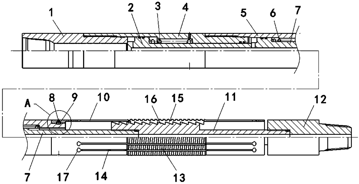
[0015] Embodiment of the present invention: hydraulic casing scraper such as figure 1 As shown, it includes an outer tube part and a core rod part arranged in the outer tube part. The outer tube part includes a piston cylinder 4, a spline body 5 and a scraper body 10. The upper joint 1 is threadedly connected to the upper end of the piston cylinder 4. The lower end of the piston cylinder 4 is threadedly connected to the upper end of the spline body 5, and the scraper body 10 is fixedly connected to the lower end of the spline body 5 by a locking screw 8; the core rod part includes a piston rod 2, a spline shaft 7 and a thread The pusher shaft 11 connected to the lower end of the spline shaft 7, the lower joint 12 is threadedly connected to the lowe...


PUM


Abstract

The invention discloses a hydraulic sleeve scraping device and method. The hydraulic sleeve scraping device comprises an outer sleeve part and a core bar part arranged in the outer sleeve part; the outer sleeve part comprises a piston cylinder, a spline body and a scraper body; an upper joint is in threaded connection with the upper end of the piston cylinder, and the lower end of the piston cylinder is in threaded connection with the upper end of the spline body; and the scraper body is fixedly connected to the lower end of the spline body through a locking screw. The sleeve scraping device can be put into a well together with a well drilling tool, and when sleeve scraping is not needed, the sleeve scraping device only serves as a part of the drilling tool to achieve the effects of connecting and power transmitting; when a well drilling process is normally implemented, a push broach shaft in the tool is located on the mounting position all the time under the elastic effect of an internal spring, and a push broach body is not expanded; and when sleeve scraping is needed, the push broach shaft can move downwards and pushes the scraper body away to conduct sleeve scraping only by increasing the mud displacement and overcoming elastic force of the spring.

Description

technical field [0001] The invention relates to a hydraulic casing scraper and a scraper method, belonging to the technical field of downhole tools. Background technique [0002] The main purpose of the hydraulic casing scraper is to remove cement, sand, scratches, paraffin, burrs and other attachments on the inner wall of the downhole casing, so that the inner wall of the casing becomes clean, so as to facilitate the normal operation of other drilling processes. The inner wall of the casing of the packer must be a clean sealing surface, so keeping the inner wall of the casing smooth and clean is a must for the entire drilling process. [0003] Most of the existing pipe scrapers use compressed springs as the scraping force of the scraper. The springs of this method are always in a compressed state from factory to use, and often have insufficient elasticity during use, resulting in unclean scraping. There is also a scraper using a spring sheet. This type of scraper is diffic...

Claims


Application Information

Patent Timeline
Patent Type & Authority Applications(China)
IPC IPC(8): E21B37/04
CPCE21B37/04
Inventor 郑波强黄保黔冯相尧张磊沈赤卫
Owner GUIZHOU GAOFENG GASOLINEEUM MACHINERY
Why Eureka
Try Eureka