An automated astigmatism or spotlight lighting equipment
A technology of lighting equipment and astigmatism, which is applied in the field of lighting decoration, and can solve problems such as inability to match the stage scene and insufficient changeability of lamps and lanterns.
- Summary
- Abstract
- Description
- Claims
- Application Information
AI Technical Summary
Problems solved by technology
Method used
Image
Examples
Embodiment 1
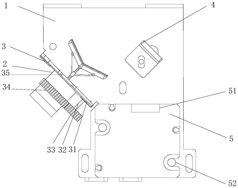
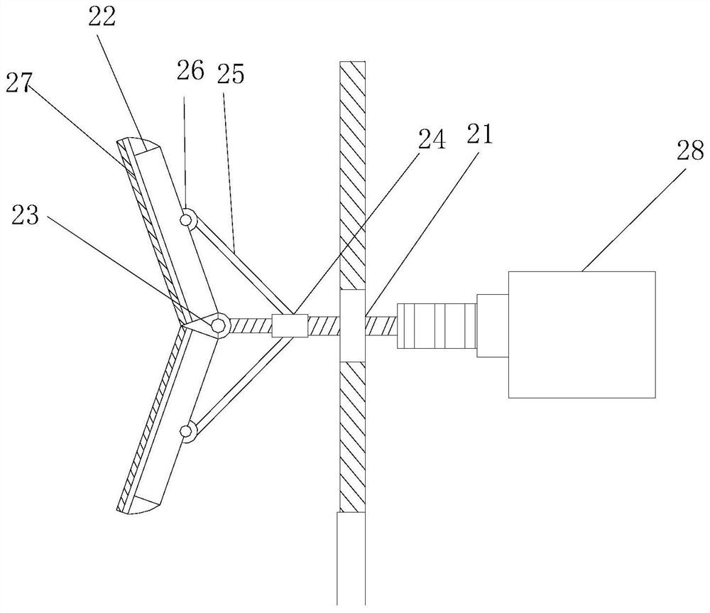
[0026] see figure 1 and figure 2 , an automatic astigmatism or spotlight lighting equipment, including a base plate 1, a spotlight base 5, a primary refraction frame 4 and a secondary refraction frame 2 are installed on the base plate 1, and the spotlight base 5 is fixed by a fixing bolt 52 Installed on the substrate 1, the front end of the spotlight holder 5 is provided with a light source port 51, the primary refraction frame 4 is installed directly in front of the light source port 51, and the secondary refraction frame 2 is set on the primary refraction frame On the side of the frame 4, the inner cavity of the secondary refraction frame 2 is inclined with respect to the base plate and is equipped with a threaded rod 21. 23 is connected to the front end of the threaded rod 21. The refraction plate 22 is composed of two concave plates, and the concave plate is combined with the hinge pin 23 and the pull rod 25 to form a concave structure.
[0027] The threaded rod 21 is e...
Embodiment 2
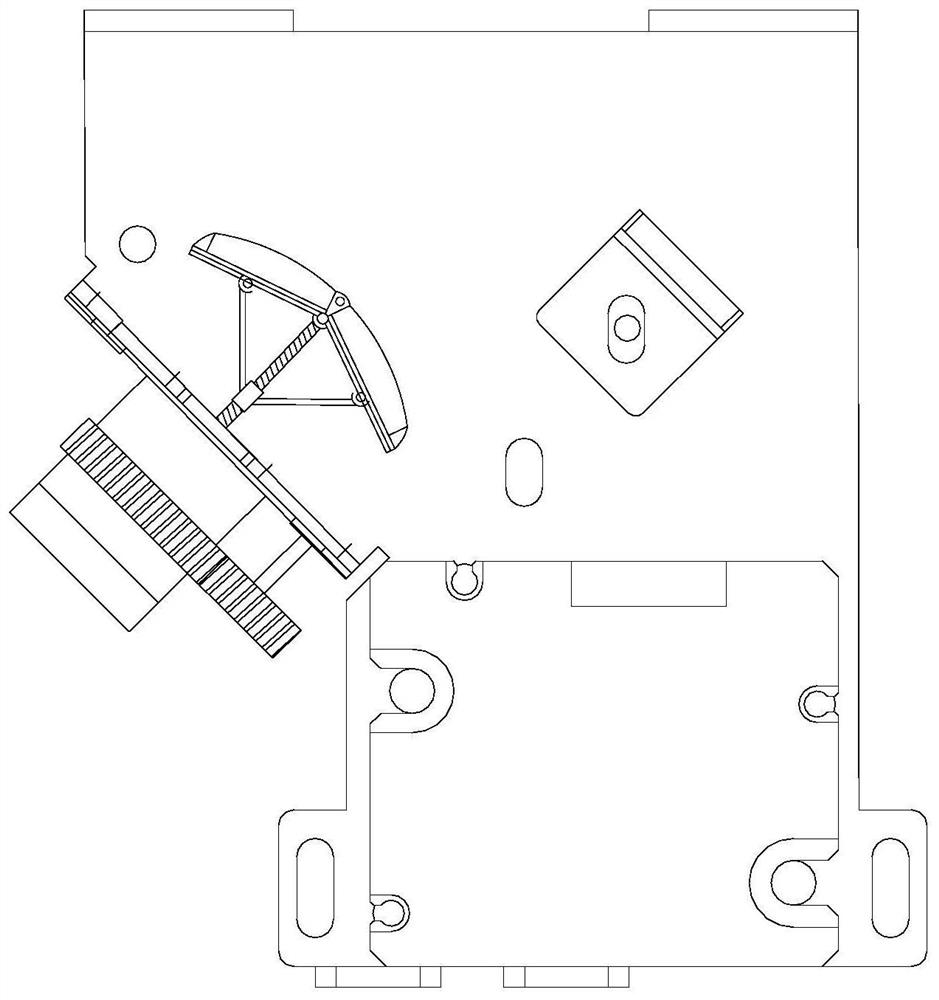
[0032] see image 3 , this embodiment is a further optimization of Embodiment 1. On the basis of it, the refraction plate 22 is composed of two convex plates, and the convex plate is combined with the hinge pin 23 and the pull rod 25 to form a convex shape. Type structure, compared with Embodiment 1, the working principle of this embodiment is the same, the difference is that the refraction plate 22 is designed as a convex structure, so that the effect of converging light source in Embodiment 1 is transformed into the effect of diffusing light source.
Embodiment 3
[0034] see Figure 4 , this embodiment is a further optimization of Embodiment 1. On the basis of this, the primary refraction frame 4 is installed on the base plate 1 through a movable base 41, and a transmission disc 43 is installed on the side wall of the base plate 1. The transmission A transmission connecting rod 44 is installed on the edge of the disk surface of the disk 43, and a connecting seat 46 is installed on the rear side of the movable base 41. The end of the driving connecting rod 44 is connected with the connecting seat 46. There is a steering motor, the motor of the steering motor is connected with the roller shaft 42 of the transmission disc 43, and an orientation sleeve 45 is installed on the plane of the substrate 1, and the transmission connecting rod 44 is limited in the orientation sleeve 45, and the steering motor Drive the transmission disk 43 to move, the transmission disk 43 drives the transmission connecting rod 44 to move, and the whole crank trans...
PUM
 Abstract
Description
Claims
Application Information
 - R&D
- Intellectual Property
- Life Sciences
- Materials
- Tech Scout
- Unparalleled Data Quality
- Higher Quality Content
- 60% Fewer Hallucinations
Browse by: Latest US Patents, China's latest patents, Technical Efficacy Thesaurus, Application Domain, Technology Topic, Popular Technical Reports.
© 2025 PatSnap. All rights reserved.Legal|Privacy policy|Modern Slavery Act Transparency Statement|Sitemap|About US| Contact US: help@patsnap.com


