
Automatic astigmatic or concentrated light lighting device

A lighting equipment and astigmatism technology, applied in the field of lighting, can solve the problems of insufficient transformability of lamps and inability to match the stage scene, etc.

Active Publication Date: 2019-03-08
CHINA HELON EXPLOSION PROOF ELECTRIC
View PDF5 Cites 2 Cited by
  • Summary
  • Abstract
  • Description
  • Claims
  • Application Information

AI Technical Summary

Problems solved by technology

[0003] Chinese patent (authorized announcement number: CN207740870U) discloses an ornamental LED lamp for stage lighting equipment. The lamp has insufficient changeability and cannot match the scene of the stage to quickly create suitable lighting. Therefore, a device that can automatically switch lights is needed. device

Method used


Image

  • Automatic astigmatic or concentrated light lighting device
  • Automatic astigmatic or concentrated light lighting device
  • Automatic astigmatic or concentrated light lighting device

Examples


Embodiment 1

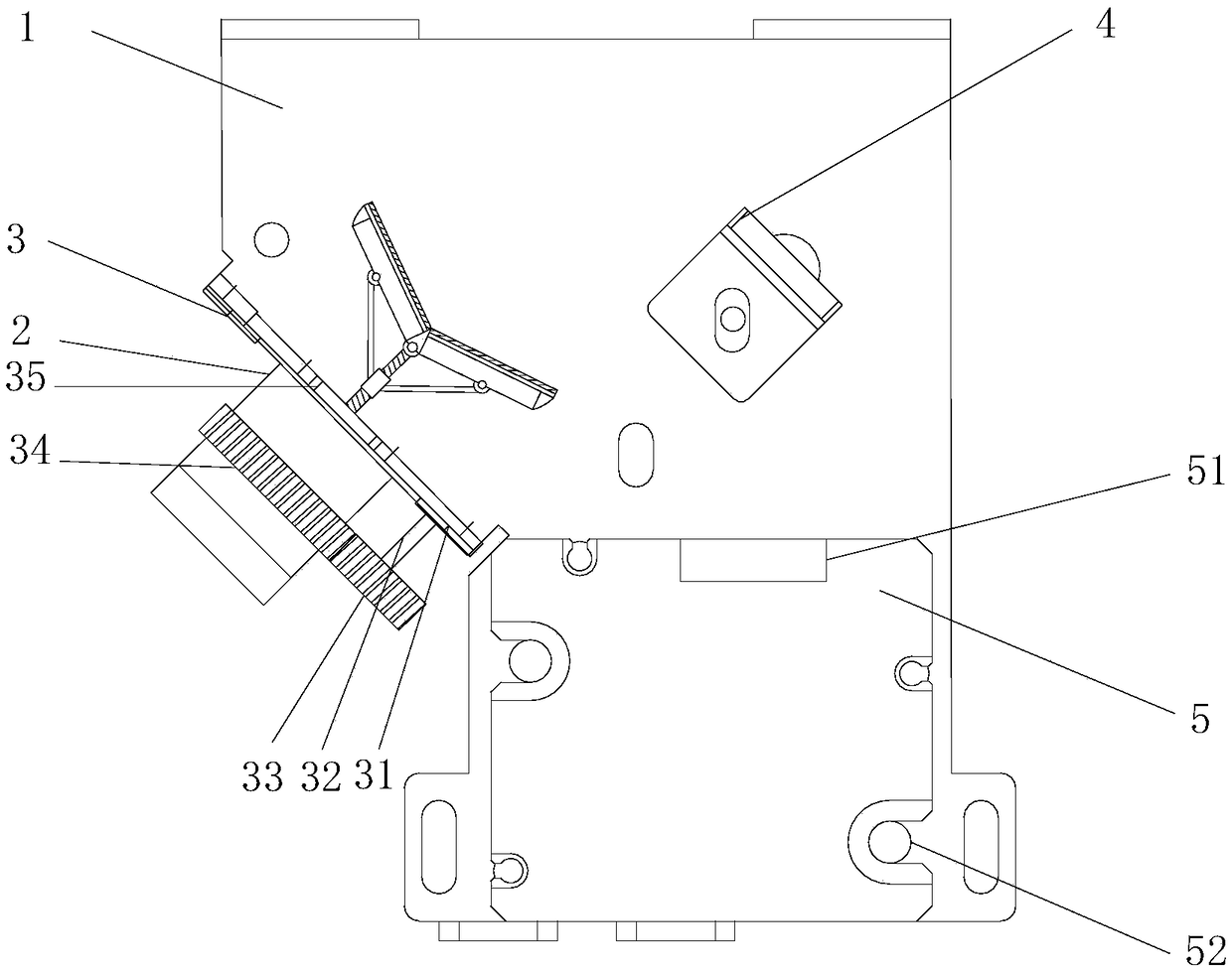
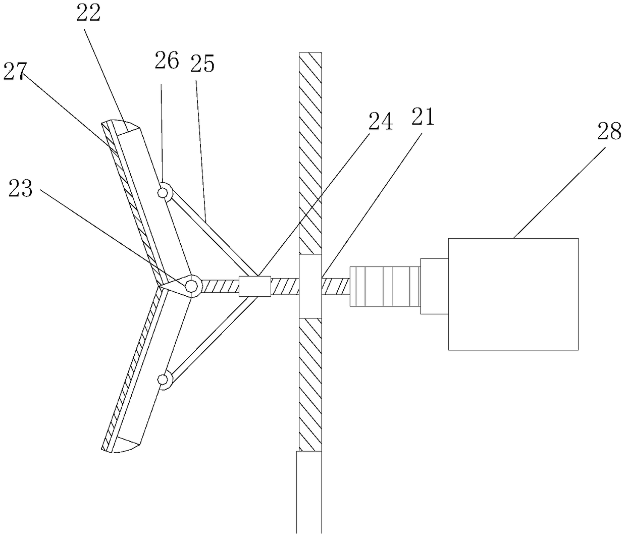
[0026] see figure 1 with figure 2 , an automatic astigmatism or spotlight lighting equipment, including a base plate 1, a spotlight base 5, a primary refraction frame 4 and a secondary refraction frame 2 are installed on the base plate 1, and the spotlight base 5 is fixed by a fixing bolt 52 Installed on the substrate 1, the front end of the spotlight holder 5 is provided with a light source port 51, the primary refraction frame 4 is installed directly in front of the light source port 51, and the secondary refraction frame 2 is set on the primary refraction frame The side of the frame 4, the inner cavity of the secondary refraction frame 2 is obliquely installed with a threaded rod 21, and the front end of the threaded rod 21 is equipped with a refraction plate 22, and the refraction plate 22 is connected to the screw thread through the hinge shaft bolt 23. The front end of the rod 21 is connected, and the refraction plate 22 is composed of two concave plates, and the conca...

Embodiment 2

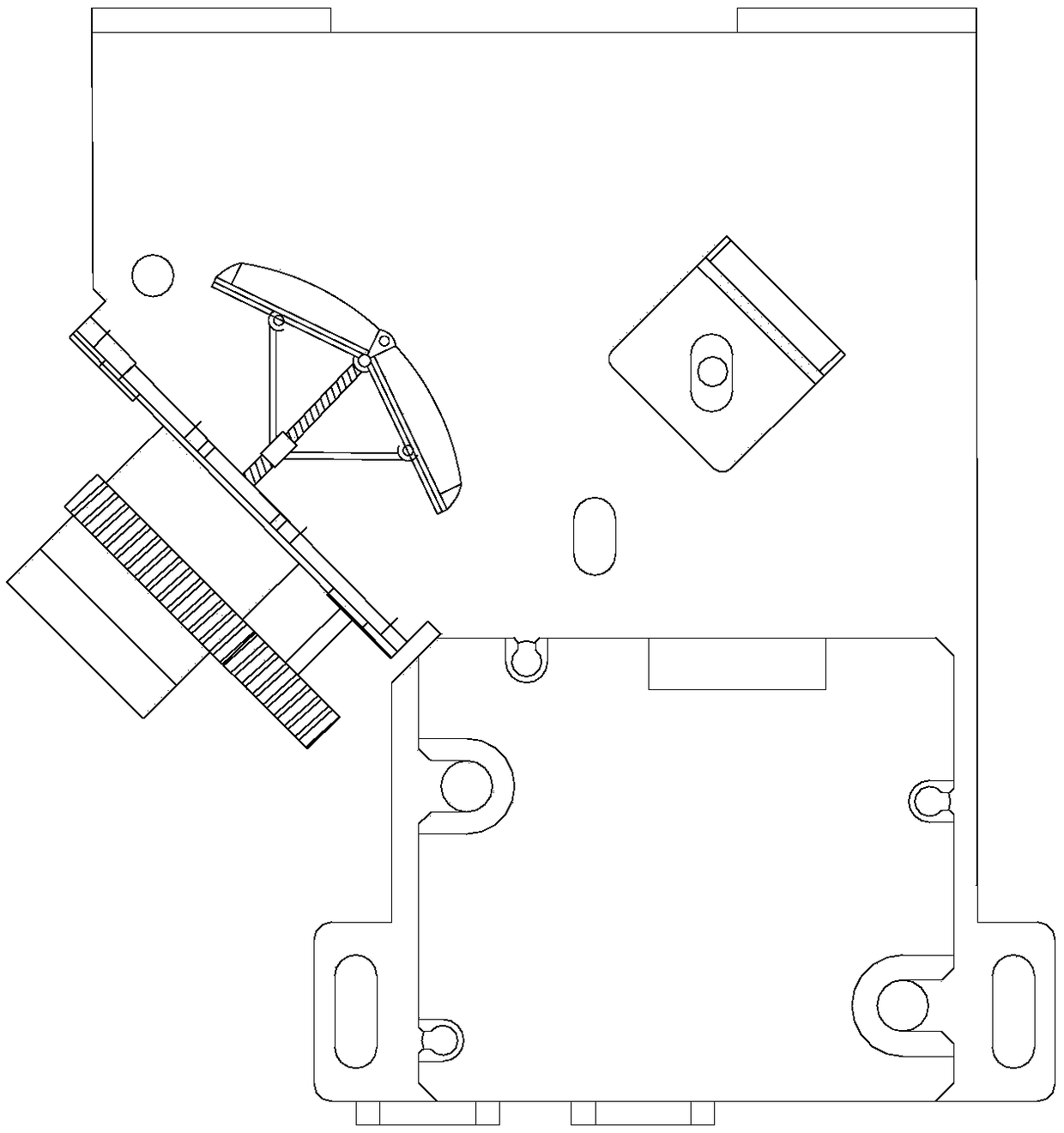
[0032] see image 3 , this embodiment is a further optimization of Embodiment 1. On the basis of it, the refraction plate 22 is composed of two convex plates, and the convex plate is combined with the hinge pin 23 and the pull rod 25 to form a convex shape. type structure. Compared with the first embodiment, the working principle of this embodiment is the same, the difference is that the refraction plate 22 is designed as a convex structure, so that the effect of converging light sources in the first embodiment is transformed into the effect of diffusing light sources.

Embodiment 3

[0034] see Figure 4 , this embodiment is a further optimization of Embodiment 1. On the basis of this, the primary refraction frame 4 is installed on the base plate 1 through a movable base 41, and a transmission disc 43 is installed on the side wall of the base plate 1. The transmission A transmission connecting rod 44 is installed on the edge of the disk surface of the disk 43 , and a connecting seat 46 is installed on the rear side of the movable base 41 , and the end of the driving connecting rod 44 is connected with the connecting seat 46 . A steering motor is installed on the side wall of the base plate 1, the motor of the steering motor is connected with the roller shaft 42 of the transmission disc 43, an orientation sleeve 45 is installed on the upper plane of the base plate 1, and the transmission connecting rod 44 is limited in the orientation Set 45 inside. The steering motor drives the transmission disc 43 to move, the transmission disc 43 drives the transmission...


PUM


Abstract

The invention relates to the field of lighting decoration, in particular to an automatic astigmatic or concentrated light lighting device. The automatic astigmatic or concentrated light lighting device comprises a base plate, a lamp refracting holder, a first-stage refracting frame and a second-stage refracting frame are installed on the base plate, the first-stage refracting frame is directly installed in front of a lamp source port, and the second-stage refracting frame is arranged on the side edge of the first-stage refractor frame. A threaded rod is arranged in an inner cavity of the second-stage refracting frame in an incline shape, refracting plates are installed at the front end of the threaded rod, and the refracting plates are connected with the front end of the threaded rod through a closing shaft bolt. A transmission sleeve is installed on the threaded rod, fixing bolts are installed on the rear sides of the refracting plates, and the transmission sleeve and the fixing boltsare connected through pull rods correspondingly. Through a thread transmission mechanism and a connecting rod transmission mechanism, an angle of refraction is changed, so that the diffusion range oflight is changed, then the concentration or astigmatism of light is adjusted, and the automatic astigmatic or concentrated light lighting device is used for meeting the demand of the field.

Description

technical field [0001] The invention relates to the field of lighting decorations, in particular to an automatic astigmatism or spotlight lighting equipment. Background technique [0002] The lighting market is extremely rich in varieties, with ever-changing shapes and performances. The aesthetic feeling of lamps and lanterns is very important, and lamps and lanterns with beautiful color and good shape can bring pleasure to people. Since lighting fixtures are an integral part of the entire room decoration, their style, material and illuminance must be consistent with the interior function and decoration style. Its ultimate purpose is to make all kinds of light-receiving objects around the lamps evenly distributed, so that people's visual functions can play a good role. With the development of the times, now whether it is a theater, a stage, a square or a large gathering or even a private party, lighting has become an indispensable and important factor. [0003] Chinese pa...

Claims


Application Information

Patent Timeline
IPC IPC(8): F21S8/00F21V5/00F21V7/00F21V14/06F21Y115/10
CPCF21S8/00F21V5/00F21V7/00F21V14/06F21Y2115/10
Inventor 魏国艳
Owner CHINA HELON EXPLOSION PROOF ELECTRIC
Learn More