Electrical-control liquid crystal plane diffractive micromirror and manufacturing method thereof

A diffractive micromirror and liquid crystal technology, applied in the field of optical lenses, can solve the problems of reducing infrared beam shaping, transformation or control efficiency, beam control efficiency, high spectral range, transmission light loss, etc., to achieve good intelligent characteristics, high incidence The effect of light wave utilization and convenient plugging

Active Publication Date: 2019-03-08
NANJING OPY ELECTRONICS TECH CO LTD
View PDF9 Cites 6 Cited by
  • Summary
  • Abstract
  • Description
  • Claims
  • Application Information

AI Technical Summary

Problems solved by technology

[0005] In view of the above defects or improvement needs of the prior art, the present invention provides an electronically controlled liquid crystal plane diffraction micromirror and a preparation method thereof, the purpose of which is to solve the technical problem of transmission light loss in the existing liquid crystal diffraction It is a technical problem based on the frequency signal driving that will adversely affect the thermal properties of the liquid crystal material, and the technical problem that the intermittent linear groove will significantly reduce the shaping, transformation or control efficiency of the infrared beam, and has high beam control efficiency , wide spectral range, good optical field adaptability, and easy coupling with other optical, optoelectronic and mechanical structures

Method used


Image

  • Electrical-control liquid crystal plane diffractive micromirror and manufacturing method thereof
  • Electrical-control liquid crystal plane diffractive micromirror and manufacturing method thereof
  • Electrical-control liquid crystal plane diffractive micromirror and manufacturing method thereof

Examples


Embodiment Construction

[0053] In order to make the object, technical solution and advantages of the present invention clearer, the present invention will be further described in detail below in conjunction with the accompanying drawings and embodiments. It should be understood that the specific embodiments described here are only used to explain the present invention, not to limit the present invention. In addition, the technical features involved in the various embodiments of the present invention described below can be combined with each other as long as they do not constitute a conflict with each other.

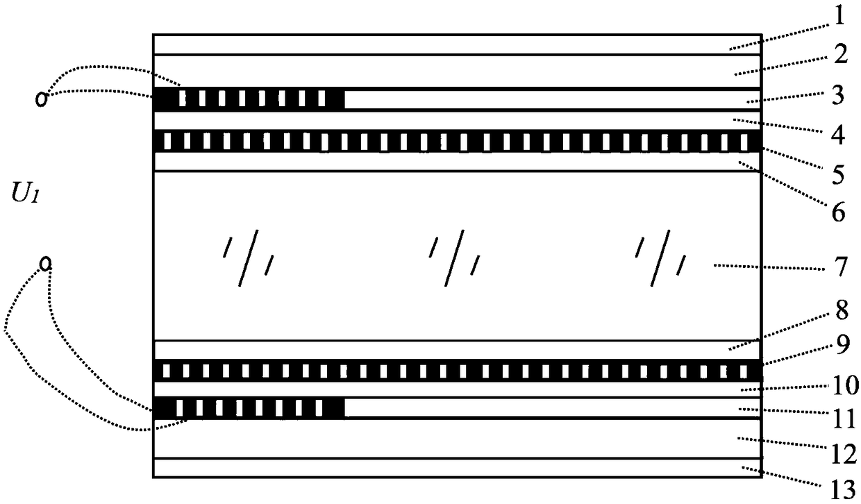
[0054] Such as figure 1 As shown, the electronically controlled liquid crystal plane diffraction micromirror of the present invention includes a first anti-reflection film 1, a first substrate 2, a first patterned electrode lead layer 3, a first insulating layer 4, a first Pattern electrode 5, first liquid crystal alignment layer 6, liquid crystal layer 7, second liquid crystal alignment layer ...


PUM

PropertyMeasurementUnit
thicknessaaaaaaaaaa
thicknessaaaaaaaaaa
thicknessaaaaaaaaaa

Abstract

The invention discloses an electrical-control liquid crystal plane diffractive micromirror, comprising a first substrate, a first pattern electrode conductor layer, a first insulating layer, a first pattern electrode, a first liquid crystal alignment layer, a liquid crystal layer, a second liquid crystal alignment layer, a second pattern electrode, a second insulating layer, a second pattern electrode conductor layer and a second substrate; each of the first pattern electrode and the second pattern electrode comprises multiple electric-driven loop electrodes which are of the same shape and areunclosed rings; the first pattern electrode conductor layer is provided with a plurality of through holes, and the number of the though holes is the same with that of total terminals of the electric-driven loop electrodes. The electrical-control liquid crystal plane diffractive micromirror solves the technical problem of loss of incident light of the existing diffractive micromirror, and also solves the technical problem about bad influence to thermophysical property of liquid crystal material due to the driving way based on frequency signals.

Description

technical field [0001] The invention belongs to the technical field of optical lenses, and more specifically relates to an electronically controlled liquid crystal plane diffraction micromirror and a preparation method thereof. Background technique [0002] Nowadays, diffractive micromirrors have been widely used. Among them, liquid crystal diffractive micromirrors, as a new type of diffractive light control device, are usually composed of multiple diffractive phase units with the same or similar basic shape, characteristic structure and size. A typical diffractive phase unit includes a sheet-like micro-nano electrode and a liquid crystal interlayer. The control electrode of the liquid crystal diffraction micromirror presents a patterned feature, and a basic pattern segment corresponds to a sheet-shaped micro-nano electrode of the diffraction phase unit. [0003] Usually, it is necessary to fabricate the boundary anchor mode of the liquid crystal film on the control electro...

Claims


Application Information

Patent Timeline
Patent Type & Authority Applications(China)
IPC IPC(8): G02F1/133G02F1/1343G02F1/1345G02F1/295
CPCG02F1/13306G02F1/134309G02F1/13452G02F1/2955
Inventor 张新宇张汤安苏
Owner NANJING OPY ELECTRONICS TECH CO LTD
Why Eureka
Try Eureka