Circuit breaker

A circuit breaker and housing technology, applied in the field of circuit breakers to release space, solve power problems, and improve accuracy

Active Publication Date: 2019-03-08
XUJI GRP +2
View PDF6 Cites 0 Cited by
  • Summary
  • Abstract
  • Description
  • Claims
  • Application Information

AI Technical Summary

Problems solved by technology

[0003] The object of the present invention is to provide a circuit breaker to solve the problem of compact internal structure of the circuit breaker in the prior art

Method used


Image

  • Circuit breaker
  • Circuit breaker
  • Circuit breaker

Examples


Embodiment Construction

[0016] Embodiments of the present invention will be further described below in conjunction with the accompanying drawings.

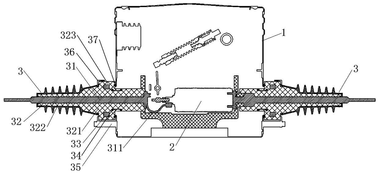
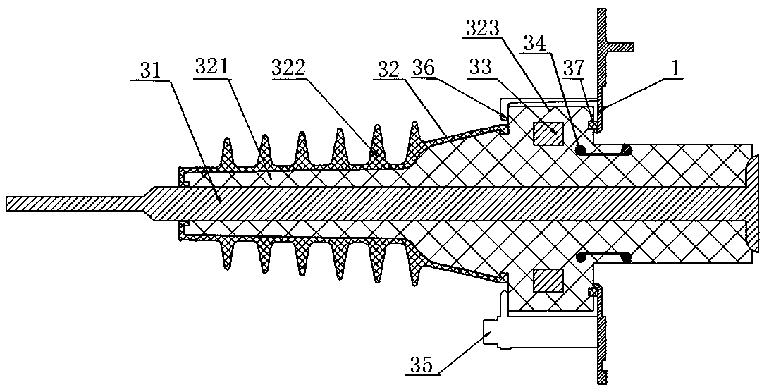
[0017] Specific embodiment 1 of the circuit breaker of the present invention, such as Figure 1 to Figure 2 As shown, the circuit breaker includes a housing 1, and an arc extinguishing chamber 2 is installed in the housing 1, and the corresponding side walls of the housing 1 are respectively provided with perforations, one side of which is perforated to form an inlet hole, and the other side is perforated to form an outlet hole , In the wire inlet hole and the wire outlet hole, a wall-through sleeve 3 is respectively worn and fixed. The structure of the wall bushing is as follows figure 2 As shown, it includes a conductive rod 31 and an insulating layer 32 surrounding the outer side of the conductive rod 31 . One end of the insulating layer 32 cantilever away from the casing 1 and the other end cantilever toward the interior of the casing 1 . One end ...


PUM


Abstract

The invention relates to a circuit breaker. The circuit breaker comprises a shell, wherein an arc extinguishing chamber is arranged in the shell, a piercing hole is arranged on the corresponding sidewall of the shell, a wall bushing is penetrated and fixed in the piercing hole, the wall bushing comprises a conductive rod and an insulating layer surrounding the conductive rod, one end of the insulating layer overhangs outwards away from the shell, and the other end of the insulating layer overhangs towards the inside of the shell to ensure that the corresponding end of the conductive rod is conductively connected with the arc extinguishing chamber, iron core windings are hermetically arranged in the part outside the shell in the insulating layer, and the iron core windings are sleeved outside the conductive rod to ensure that the iron core windings and the conductive rod form a passive electronic current sensor. The iron core windings are sleeved outside the conductive rod and form thepassive electronic current sensor together with the conductive rod, thereby, the problem of the power supply of the current sensor can be solved, the accuracy of the current sensor can also be improved, and the space inside the shell can be greatly released.

Description

technical field [0001] The invention relates to a circuit breaker. Background technique [0002] In order to improve the reliability of safe power supply, the circuit breaker is usually connected with a current transformer to detect the current. For example, the watchdog boundary load switch disclosed in the Chinese invention patent application document with application publication number CN104037011A is a circuit breaker. An insulating box and an insulating operating mechanism are installed in the body, and a vacuum interrupter is installed in the insulating box. The bushing includes an outgoing line conductive rod, one end of the outgoing line conductive rod extends into the casing and connects with the other end of the vacuum interrupter to form a conductive loop, and the casing is equipped with current transformers on both sides of the incoming line conductive rod and the outgoing line conductive rod . Since the current transformer needs to meet the requirements of sm...

Claims


Application Information

Patent Timeline
Patent Type & Authority Applications(China)
IPC IPC(8): H01H33/02H01H33/662
CPCH01H33/027H01H33/66261
Inventor 吴小钊张文凯梁利娟郅娇娇崔宇张杰赵洪柏孙广涛海战胜刘源
Owner XUJI GRP
Why Eureka
Try Eureka