
Joint waterproof detection system and detection method

A detection system and detection method technology, applied in the direction of measuring electricity, measuring devices, measuring electrical variables, etc., can solve problems such as unsuitable for detecting cable joints, difficult to eliminate interference from environmental noise, and ineffective defect detection.

Inactive Publication Date: 2020-05-15
STATE GRID BEIJING ELECTRIC POWER +2
View PDF7 Cites 4 Cited by
  • Summary
  • Abstract
  • Description
  • Claims
  • Application Information

AI Technical Summary

Problems solved by technology

[0003] 1. The dielectric loss detection method can judge whether there is a defect in the tested cable, but it cannot locate and quantitatively identify how much water has entered
[0004] 2. The time domain reflection method can judge the water ingress of the tested cable, but the reflection signal of this method is weak, and the received signal contains multiple reflections, and it is difficult to eliminate the interference of environmental noise, resulting in a low detection result accuracy
[0005] 3. Oscillating wave voltage method is more effective in detecting defects of misused insulating tape on the surface of crimping tubes, but not obvious in detecting other defects
That is to say, partial discharge is more sensitive to discharge defects, but the operating parameters of the cable in the early stage of water entering the cable joint will not change much, so the partial discharge method is not suitable for detecting whether the cable joint is wet or not.
[0007] To sum up, there is currently no effective equipment or effective means to monitor the water ingress of the cable intermediate joint

Method used


Image

  • Joint waterproof detection system and detection method
  • Joint waterproof detection system and detection method
  • Joint waterproof detection system and detection method

Examples


Embodiment Construction

[0031] In order to enable those skilled in the art to better understand the solutions of the present invention, the following will clearly and completely describe the technical solutions in the embodiments of the present invention in conjunction with the drawings in the embodiments of the present invention. Obviously, the described embodiments are only It is an embodiment of a part of the present invention, but not all embodiments. Based on the embodiments of the present invention, all other embodiments obtained by persons of ordinary skill in the art without making creative efforts shall fall within the protection scope of the present invention.

[0032] It should be noted that the terms "first" and "second" in the description and claims of the present invention and the above drawings are used to distinguish similar objects, but not necessarily used to describe a specific sequence or sequence. It is to be understood that the data so used are interchangeable under appropriate ...


PUM


Abstract

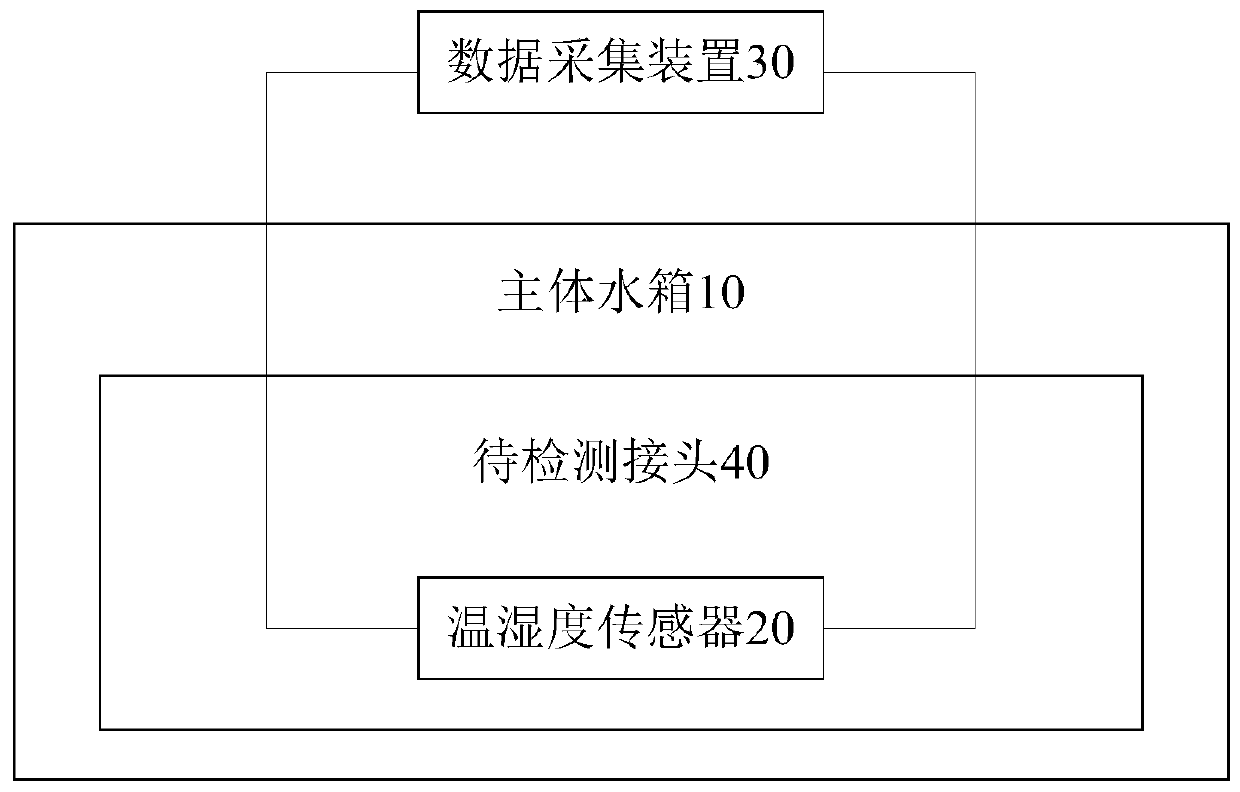
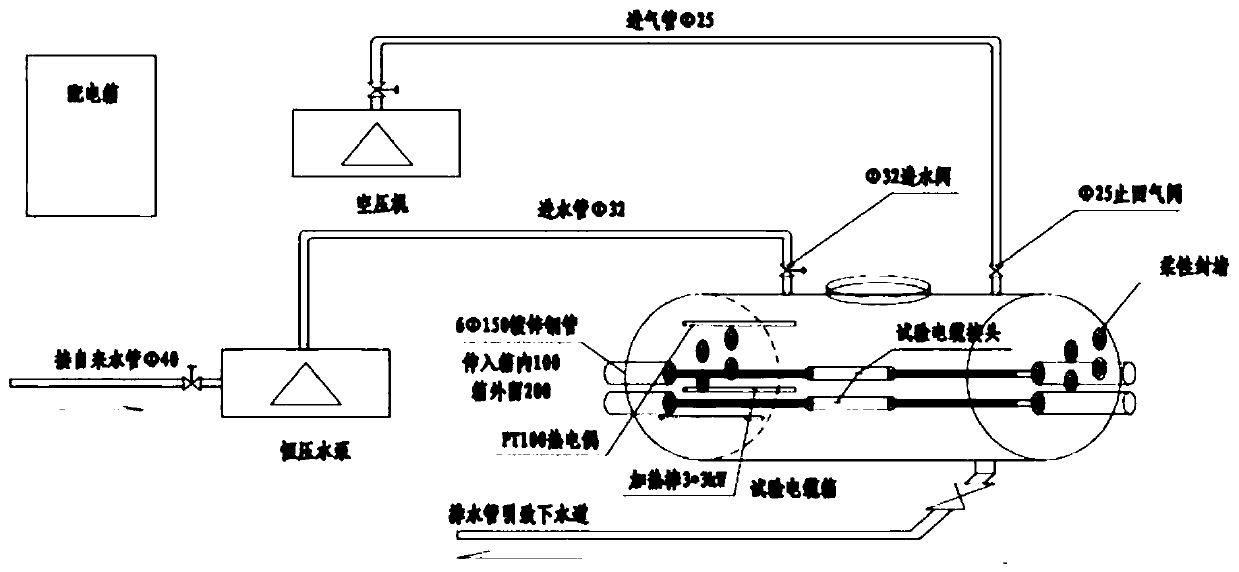
The invention discloses a joint waterproof detection system and detection method. The detection system comprises a main body water tank, a temperature and humidity sensor and a data acquisition device, wherein the temperature and humidity sensor is placed in a to-be-detected joint, the to-be-detected joint is placed in the main body water tank, the data acquisition device is in communication connection with the temperature and humidity sensor so as to determine whether the to-be-detected joint fails or not based on temperature and humidity parameters acquired by the temperature and humidity sensor; the main body water tank is provided with a water inlet, and the water inlet is connected with a water inlet valve and a constant-pressure water pump; the main water tank is provided with a water outlet, and the water inlet is connected with a drain valve; the main water tank is also connected with a circulating water pump, one end of the circulating water pump is connected with a water inlet valve of the main body water tank, and the other end of the circulating water pump is connected with a drain valve of the main body water tank through a check valve. According to the invention, theproblems of electric energy supply and temperature and humidity signal transmission of the built-in temperature and humidity sensor are solved, and the technical effect of directly measuring the temperature and humidity in the cable joint is achieved.

Description

technical field [0001] The invention relates to the field of cable joints, in particular to a joint waterproof detection system and detection method. Background technique [0002] The faults caused by water ingress and moisture in the middle joint of the cable account for about 61% of the total faults of the cable head. Water ingress and dampness of cable joints is the main cause of cable failures. At present, the cable defect detection methods put into use at home and abroad include dielectric loss method, time domain reflection method, oscillatory wave method and partial discharge method. The above-mentioned methods are introduced in detail: [0003] 1. The dielectric loss detection method can judge whether there is a defect in the tested cable, but it cannot locate and quantitatively identify how much water has entered. [0004] 2. The time domain reflection method can judge the water ingress of the tested cable, but the reflection signal of this method is weak, and the...

Claims


Application Information

Patent Timeline
IPC IPC(8): G01R31/00G01N33/00
CPCG01R31/003G01N33/00G01N33/0078
Inventor 郭卫任志刚潘泽华刘若溪徐兴全姚玉海李邦彦刘宏亮方春华杨司齐叶小源
Owner STATE GRID BEIJING ELECTRIC POWER
Learn More