Indoor distribution system and work method thereof

A technology of room division system and bridging equipment, applied in the field of room division system, can solve the problem of room division system requiring additional power supply and so on

Active Publication Date: 2017-04-19
ZTE CORP
View PDF5 Cites 4 Cited by
  • Summary
  • Abstract
  • Description
  • Claims
  • Application Information

AI Technical Summary

Problems solved by technology

[0005] The invention provides a room distribution system and its working method to sol

Method used


Image

  • Indoor distribution system and work method thereof
  • Indoor distribution system and work method thereof
  • Indoor distribution system and work method thereof

Examples


no. 1 example

[0024] figure 1 This is a schematic diagram of the structure of the compartment system provided by the first embodiment of the present invention, which is represented by figure 1 It can be seen that, in this embodiment, the room branch system provided by the present invention includes: base station equipment 1, baseband processing bridging equipment 2, and micro radio frequency remote equipment 3; the base station equipment 1 is connected to the baseband processing bridging equipment 2 through optical fibers, and the micro radio frequency pull The remote device 3 is connected to the baseband processing bridge device 2 through a network cable.

[0025] In some embodiments, the baseband processing bridge device in the foregoing embodiment is a plurality of baseband processing bridge devices, and the multiple baseband processing bridge devices are cascaded.

[0026] In some embodiments, there are multiple remote micro radio devices in the above embodiments, and the baseband processing ...

no. 2 example

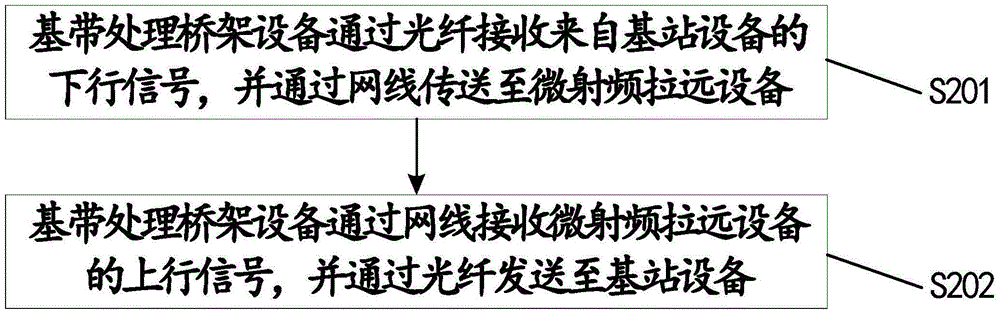
[0035] figure 2 This is a flow chart of the working method of the room division system provided by the second embodiment of the present invention. figure 2 It can be seen that, in this embodiment, the working method of the room division system provided by the present invention, which is used in the room division system provided by the present invention, includes the following steps:

[0036] S201: The baseband processing bridge device receives the downlink signal from the base station device through the optical fiber, and transmits it to the micro radio remote device through the network cable;

[0037] S202: The baseband processing bridge device receives the uplink signal of the micro radio remote device via the network cable, and sends it to the base station device via the optical fiber.

[0038] The present invention will be further explained and explained in combination with specific application scenarios.

no. 3 example

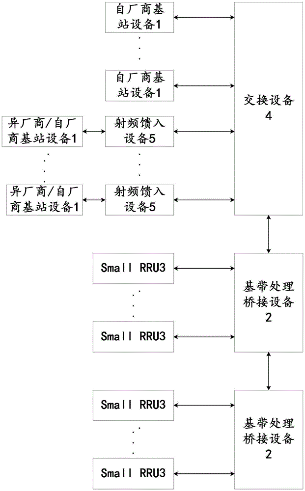
[0040] This embodiment gives a detailed description of the present invention, such as image 3 As shown, the room sub-system provided by the present invention includes: base station equipment of different frequency bands from multiple different manufacturers 1, multiple cascaded baseband processing bridging equipment 2, multiple remote micro radio equipment 3, switching equipment 4, and radio frequency feeder Access equipment 5, and network management and configuration devices not shown. Based on the indoor sub-system, this embodiment is a further supplement to the existing indoor sub-system, and proposes a multi-band, many-to-many indoor coverage system, which can be flexibly applied to wireless communication systems from different vendors and vendors. The Small RRU (micro radio frequency remote) equipment 3 used is small in size and light in weight. It does not require additional power supply equipment and is easy to install and manage. In addition, through the background net...


PUM


Abstract

The invention provides an indoor distribution system and a work method thereof. The indoor distribution system comprises a base station device, a baseband processing and bridge device and a micro radio remote device. The base station device is connected to the baseband processing and bridge device through an optical fiber, and the micro radio remote device is connected to the baseband processing and bridge device through a network cable. According to the indoor distribution system, based on that the base station device is connected to the baseband processing and bridge device through the optical fiber and the micro radio remote device is connected to the baseband processing and bridge device through the network cable, the micro radio remote device can obtain electric energy from the baseband processing and bridge device through the network cable instead of being powered by an external power supply, so that the problem that current indoor distribution systems need to be powered by extra power supplies is solved, and the arrangement of the indoor distribution system is more convenient.

Description

Technical field [0001] The invention relates to the field of wireless communication, in particular to a room division system and a working method thereof. Background technique [0002] The indoor sub-system is a solution aimed at indoor user groups and used to improve the mobile communication environment in buildings. It mainly distributes the signals of mobile base stations evenly in every corner of the room to ensure ideal signal coverage in the indoor area. [0003] The current main room sub-system solutions are: one is a repeater, based on the surplus capacity of the outdoor macro station, the signal is introduced into the blind area of ​​indoor coverage, suitable for places with concentrated traffic, and is a typical passive coverage Access method, repeater requires additional power supply, installation is inconvenient, easy to age, network management is inconvenient, and brings certain noise to the original base station; the second is microcell, which is mainly a supplement t...

Claims


Application Information

Patent Timeline
IPC IPC(8): H04L12/10
CPCH04B10/25H04L12/10
Inventor 刘祝垣王仰锋张迪强刘凯
Owner ZTE CORP
Why Eureka
Try Eureka