
Camera assembly and electronic equipment

A technology for a camera assembly and a camera module, which is applied in the field of camera assemblies and electronic equipment, can solve problems such as poor applicability and difficulty in applying electronic equipment.

Active Publication Date: 2019-03-08
HUAWEI TECH CO LTD
View PDF4 Cites 19 Cited by
  • Summary
  • Abstract
  • Description
  • Claims
  • Application Information

AI Technical Summary

Problems solved by technology

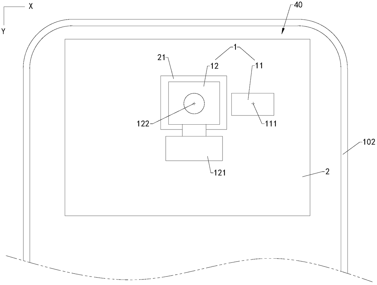
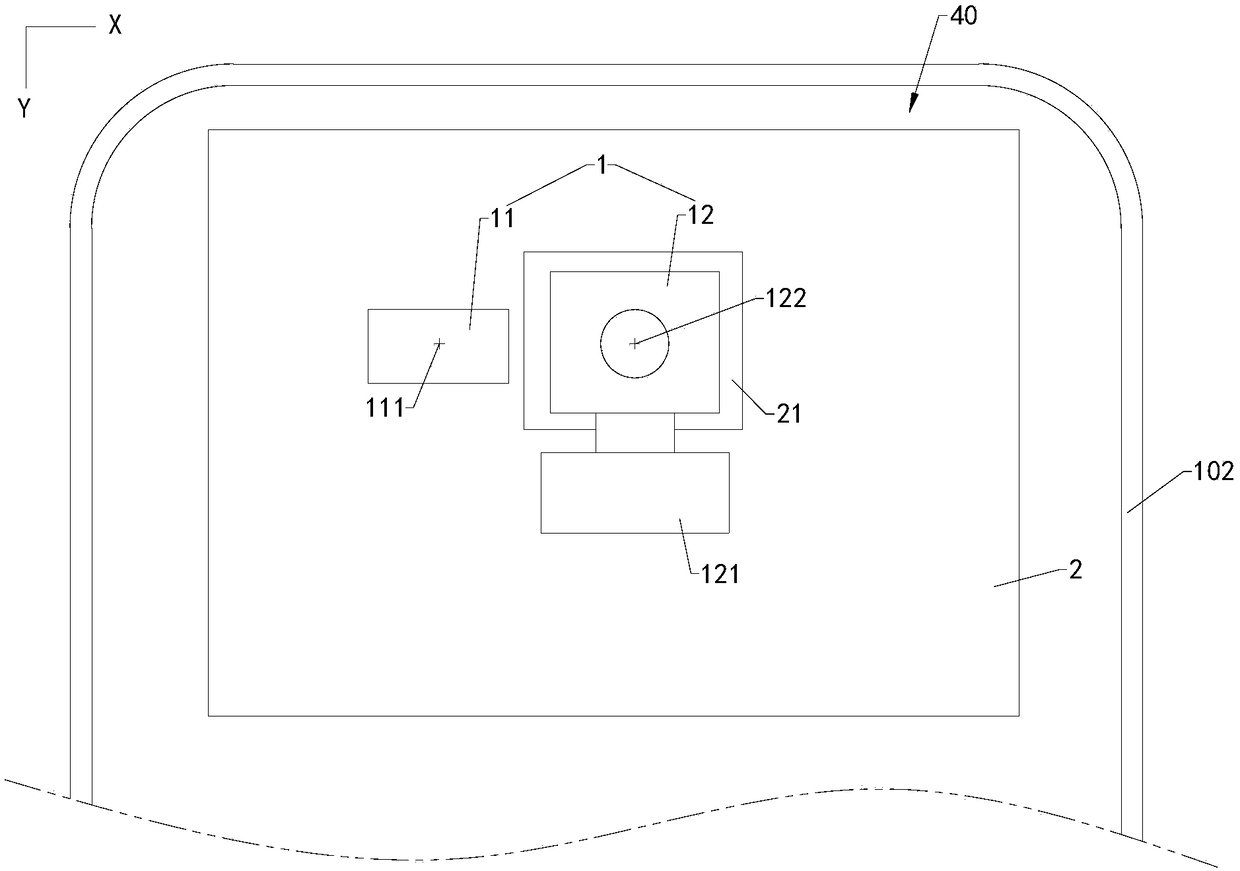
In this way, since the relative positions of the transmitting module and the receiving module and the outgoing direction of the printed circuit board have been fixed, the positions of the interaction holes facing the transmitting module and the receiving module on the cover plate of the electronic equipment using the time-of-flight module are also fixed. It is fixed, so that the time-of-flight module can only be applied to electronic equipment with a specific appearance, and it is difficult to apply to electronic equipment with other appearances, and the applicability is poor

Method used


Image

  • Camera assembly and electronic equipment
  • Camera assembly and electronic equipment
  • Camera assembly and electronic equipment

Examples


Embodiment Construction

[0049] Embodiments of the present application are described below with reference to the accompanying drawings in the embodiments of the present application.

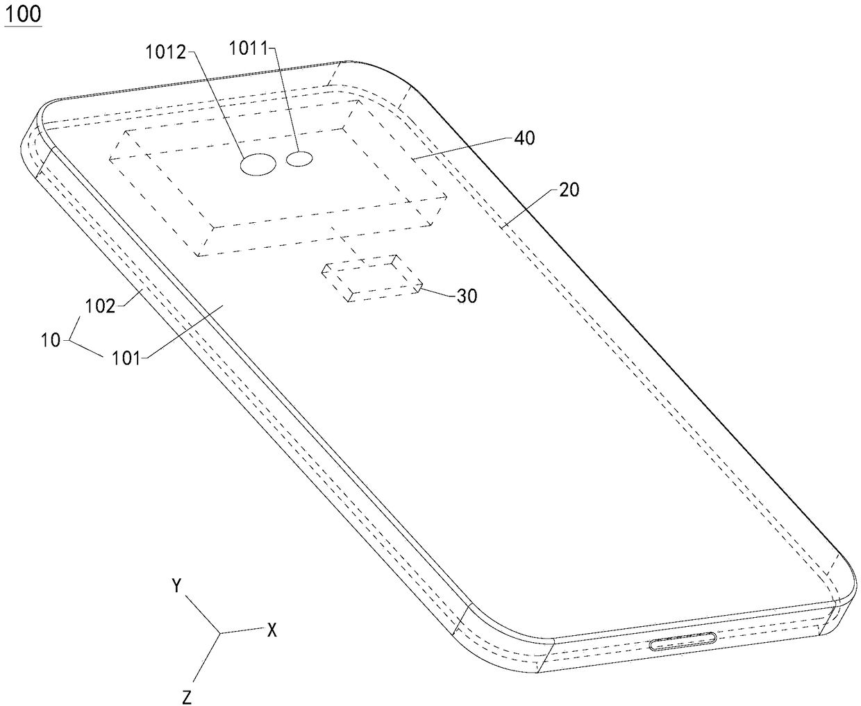
[0050] see figure 1 , figure 1 It is a schematic structural diagram of the electronic device 100 in the first embodiment provided by the embodiment of the present application. The electronic device 100 involved in this application may be a mobile phone, a tablet computer, an e-reader, a notebook computer, a vehicle-mounted device, or a wearable device. This embodiment is described by taking the electronic device 100 as a mobile phone as an example. Define the width direction of the electronic device 100 as X, the length direction of the electronic device 100 as Y, the thickness direction of the electronic device 100 as Z, the width direction X, the length direction Y and the thickness direction Z are perpendicular to each other.

[0051] The electronic device 100 includes a casing 10 and a display screen 20 . The hou...


PUM


Abstract

The embodiment of the invention discloses a camera assembly, which comprises a time-of-flight module and a circuit board, wherein the circuit board is provided with a reserved space; the time-of-flight module comprises a transmitting module and a receiving module; the transmitting module is configured to transmit a detecting optical signal, and the receiving module is used for receiving a sensingoptical signal formed by the detecting optical signal reflected by a to-be-detected object; the receiving module is located in the reserved space, and the connecting end of the receiving module is fixed on the circuit board; and the transmitting module is located at the periphery of the receiving module and is fixed on the circuit board. The above camera assembly is relatively high in practicability. The embodiment of the invention further discloses electronic equipment applying the camera assembly.

Description

technical field [0001] The present application relates to the technical field of electronic products, in particular to a camera component and an electronic device using the camera component. Background technique [0002] The main component of electronic equipment to realize the imaging function is the camera module. A time of flight (TOF) module is a commonly used depth camera module that can be used to measure depth information. The time-of-flight module includes a transmitting module and a receiving module. In order to ensure the detection performance of the time-of-flight module, the transmitting module and the receiving module usually need to be close enough so that the field of view of the transmitting module overlaps with the field of view of the receiving module. In traditional time-of-flight modules, the transmitting module and the receiving module are fixed on the same printed circuit board to meet the proximity requirements of the transmitting module and the rece...

Claims


Application Information

Patent Timeline
Patent Type & Authority Applications(China)
IPC IPC(8): H04N5/225H04M1/02
CPCH04M1/026H04M1/0264H04M1/0266H04M1/0277H04N23/50H04N23/57H04N23/55G01S17/89G01S17/08H04N5/38H04N23/54
Inventor 唐玮王娜郦光丰
Owner HUAWEI TECH CO LTD
Learn More