Electronic equipment and camera

A technology for electronic equipment and driving motors, applied in the field of data transmission, can solve problems such as signal quality degradation, and achieve the effect of increasing bandwidth

Pending Publication Date: 2019-04-23
NANJING DSEELAB DIGITAL TECH CO LTD
View PDF0 Cites 3 Cited by
  • Summary
  • Abstract
  • Description
  • Claims
  • Application Information

AI Technical Summary

Problems solved by technology

[0004] In view of this, the purpose of the embodiment of the present application is to provide an electronic device and a camera to improv

Method used


Image

  • Electronic equipment and camera
  • Electronic equipment and camera
  • Electronic equipment and camera

Examples


no. 1 example

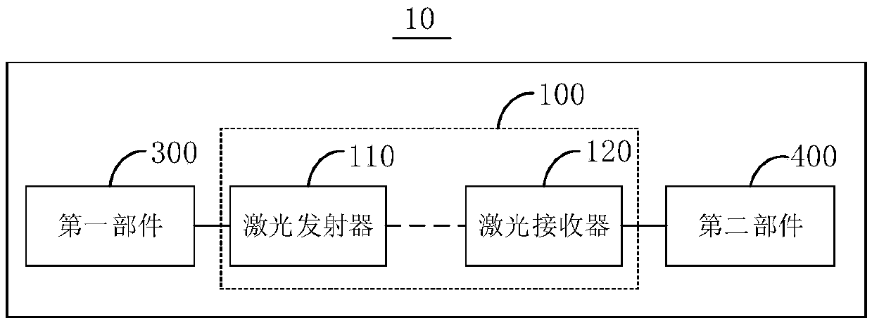
[0050] For details, please refer to figure 1 , figure 1 A structural block diagram of the electronic device 10 provided by the embodiment of the present application is shown. Wherein, the electronic device 10 may be a display device that needs to be rotated, may also be a camera pan / tilt, or may be a laser radar. Such as figure 1 As shown, the electronic device 10 includes: a data transmission device 100, a drive motor 200 (see figure 2 ), the first component 300, and the second component 400.

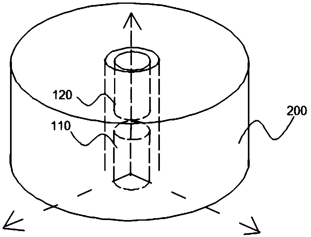
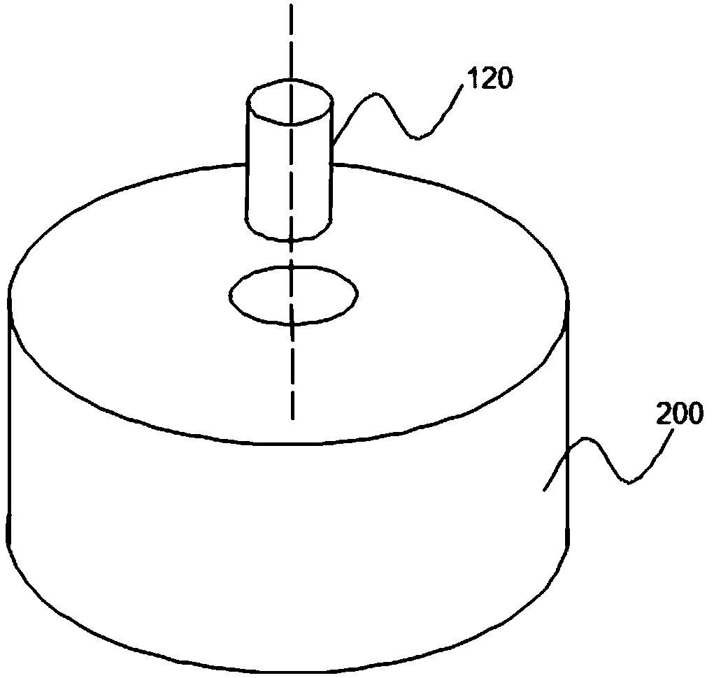
[0051] The driving motor 200 is arranged between the first part 300 and the second part 400, the driving motor 200 is used to drive the first part 300 to rotate or to drive the second part 400 to rotate, the first part 300 is used to transmit data to the data transmission device 100, The second component 400 is used for receiving data transmitted by the data transmission device 100 . The driving motor 200 is provided with a through hole, and the data transmission device 100 is in...

no. 2 example

[0087] This embodiment provides a display device, which is a form of expression of the electronic device in the foregoing embodiments, and the display device may be a rotating LED holographic display device. Such as Figure 6 As shown, the display device includes a bottom plate, a data transmission device 100 ( Figure 6 not shown), drive motor 200, power supply coil 500, control board 420, lamp board 410. The driving motor 200 may be a disc motor, such as a pan-tilt motor or an air-axis motor.

[0088] The backplane can store or receive multimedia data. The light board 410 is provided with a light bar or several LED arrays. The light board 410 can receive the multimedia data sent by the backplane through the data transmission device 100, and control the light bar or LED array to change the display content according to the received multimedia data to form a holographic image. screen.

[0089] The driving motor 200 is arranged between the bottom board and the control board ...

no. 3 example

[0098] This embodiment provides a camera (not shown in the figure), which includes a capture device and the electronic device 10 provided in the aforementioned first embodiment.

[0099] The collection device is connected to the second component 400 of the electronic device 10 ; the collection device is used to take pictures according to the instruction output by the electronic device 10 . The collection device may be a camera.

[0100] For other details of the camera in this embodiment, further reference may be made to the relevant description of the electronic device 10 in the foregoing embodiment, which will not be repeated here.

[0101] Through the above structure, the electronic device 10 with high signal transmission quality can be used to realize data transmission, and the acquisition device can shoot according to the command output by the electronic device 10, which is beneficial to the work of the camera that needs to rotate and shoot, and the shooting process is mor...


PUM


Abstract

Embodiments of the invention provide electronic equipment and a camera. The electronic equipment comprises a driving motor, a data transmission device, a first component and a second component, wherein the driving motor is arranged between the first component and the second component; the driving motor is used for driving the first component to rotate or driving the second component to rotate; thefirst component is used for transmitting data to the data transmission device, and the second component is used for receiving the data transmitted by the data transmission device; the data transmission device comprises a laser emitter and a laser receiver, a through hole is arranged in the drive motor, and the laser emitter and the laser receiver are arranged in the extending direction of the through hole; and the laser receiver is used for receiving the laser which is emitted by the laser emitter and passes through the through hole in order to achieve data transmission between the first component and the second component.

Description

technical field [0001] This application relates to the field of data transmission, in particular, to an electronic device and a video camera. Background technique [0002] In recent years, with the continuous development of holographic display technology, various holographic display devices have gradually come into public view, and rotating LED (Light Emitting Diode, light emitting diode) holographic display devices are no exception. However, because it is an emerging industry, many devices are not mature in technology, and it is difficult to meet the increasingly complex market needs. [0003] Limited by the structural particularity of the rotating LED holographic display device, slip rings are generally used to realize the communication between the rotating part and the fixed part. However, slip rings are prone to signal quality degradation due to poor contact, making it difficult to adapt to market demand. Contents of the invention [0004] In view of this, the purpos...

Claims


Application Information

Patent Timeline
IPC IPC(8): H04N5/232G05D3/12H04B10/50
CPCH04B10/503G05D3/12H04N23/66
Inventor 罗鸿飞胡航
Owner NANJING DSEELAB DIGITAL TECH CO LTD
Why Eureka
Try Eureka