
Driving method and driving device of display panel

A technology of display panel and driving method, which is applied to static indicators, instruments, etc., and can solve problems such as uneven panel display

Inactive Publication Date: 2019-03-15
SHENZHEN CHINA STAR OPTOELECTRONICS TECH CO LTD
View PDF4 Cites 18 Cited by
  • Summary
  • Abstract
  • Description
  • Claims
  • Application Information

AI Technical Summary

Problems solved by technology

[0004] The purpose of the present invention is to provide a driving method and a driving device of a display panel, which can solve the problem of uneven display of the panel

Method used


Image

  • Driving method and driving device of display panel
  • Driving method and driving device of display panel
  • Driving method and driving device of display panel

Examples


Embodiment Construction

[0018] In order to make the purpose, technical means and effects of the present invention clearer, the present invention will be further elaborated below in conjunction with the accompanying drawings. It should be understood that the embodiments described here are only some, not all, embodiments of the present invention, and are not intended to limit the present invention.

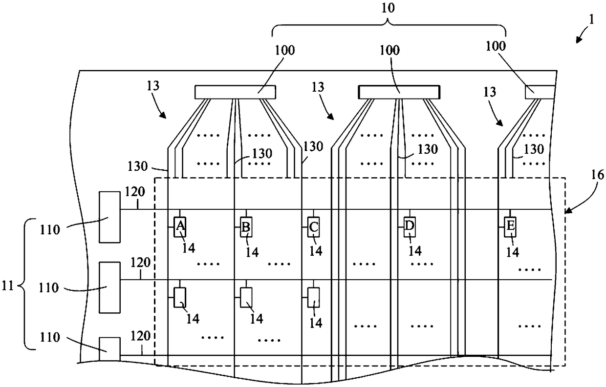
[0019] Please refer to figure 1 , which shows a schematic structural diagram of a display panel provided by an embodiment of the present invention. The display panel 1 includes a source driving circuit 10 , a gate driving circuit 11 , a plurality of gate signal lines 120 electrically connected to the gate driving circuit 11 , and a plurality of data lines 130 electrically connected to the source driving circuit 10 . In the embodiment of the present invention, the gate driving circuit 11 includes a plurality of gate drivers 110 , and each gate driver 110 is electrically connected to each gate signal line 1...


PUM


Abstract

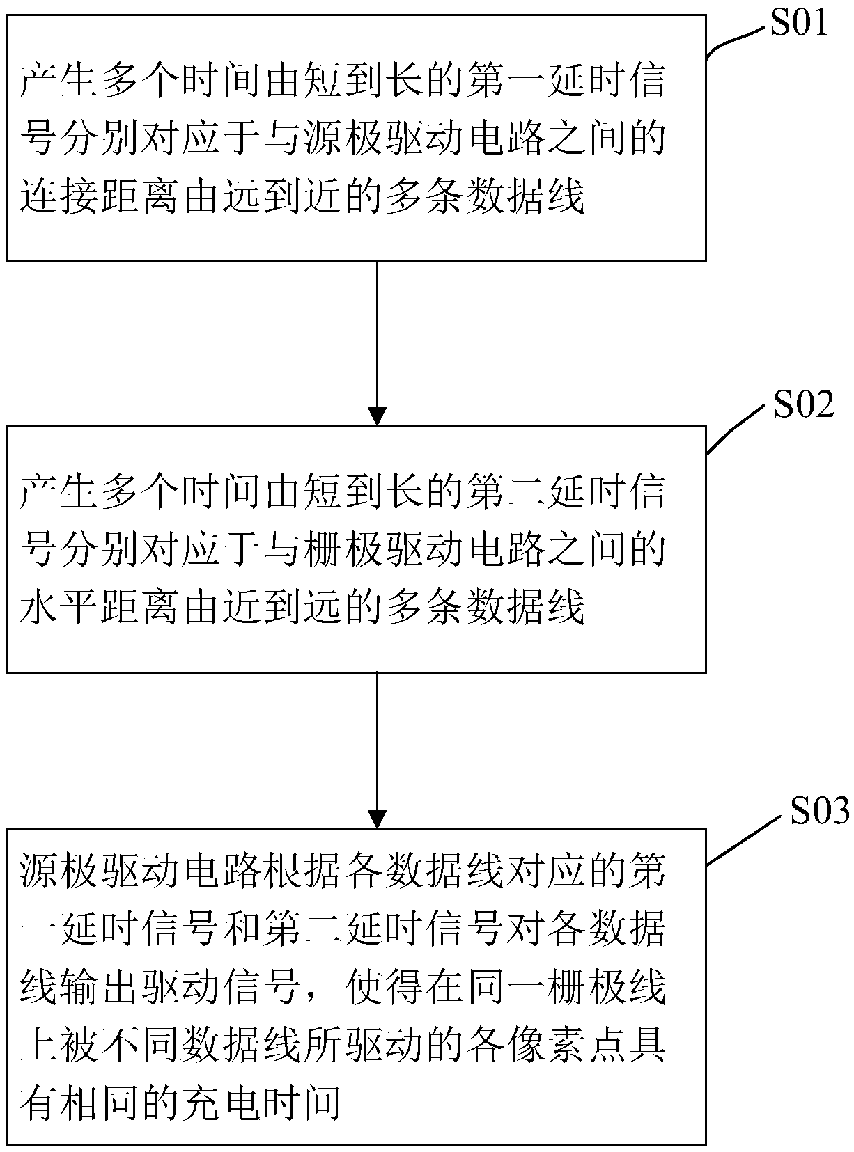
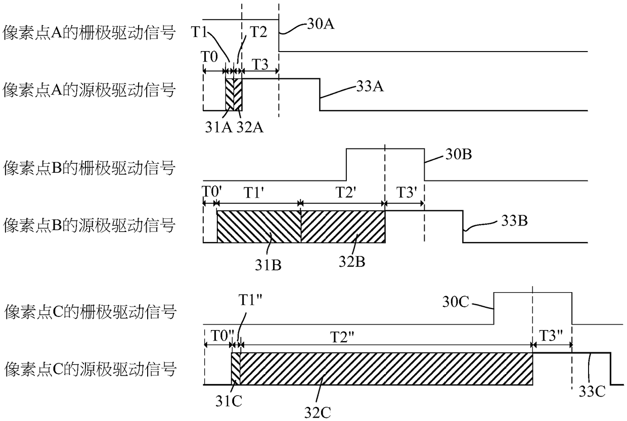
The invention relates to a driving method and a driving device of a display panel. The display panel comprises a source driving circuit, a gate driving circuit, a plurality of gate signal lines electrically connected to the gate driving circuit, and the data lines electrically connected to the source driving circuit. The driving method comprises the following steps of: generating the first delay signals with time from short to long respectively corresponding to the data lines from a far to near connection distance with the source driving circuit. Then, generating the second delay signals withtime from short to long respectively corresponding to the data lines from a near to far horizontal distance with the gate driving circuit. Finally, the source driving circuit outputs driving signals to each data line according to the first delay signal and the second delay signal corresponding to each data line, so that each pixel point driven by different data lines on the same gate line has thesame charging time.

Description

technical field [0001] The present invention relates to the field of display technology, in particular to a driving method and a driving device of a display panel. Background technique [0002] When the existing liquid crystal panel drives pixels at different positions, the connection distance between each pixel and the driver is not equal, that is, the transmission impedance is inconsistent, resulting in a charging delay difference (RC delay). When the same timing driving signal is used, the actual charging time of each pixel is not the same, which will lead to uneven panel display or color shift. For large-size panels, the problem of uneven display will be more obvious due to the greater transmission impedance of the signal lines. [0003] Therefore, it is necessary to provide a driving method and a driving device of a display panel to solve the above problems. Contents of the invention [0004] The object of the present invention is to provide a driving method and a d...

Claims


Application Information

Patent Timeline
Patent Type & Authority Applications(China)
IPC IPC(8): G09G3/36
CPCG09G3/3677G09G3/3688
Inventor 陈小龙
Owner SHENZHEN CHINA STAR OPTOELECTRONICS TECH CO LTD
Learn More