A temperature-controlled swimming type swirl gas well drainage plunger

A swimming, drainage column technology, applied in the production of fluids, wellbore/well components, machines/engines, etc., to achieve a large contribution rate, avoid premature flooding and stop production, and achieve significant technical effects

Active Publication Date: 2020-11-27
CHENGDU UNIVERSITY OF TECHNOLOGY
View PDF7 Cites 0 Cited by
  • Summary
  • Abstract
  • Description
  • Claims
  • Application Information

AI Technical Summary

Problems solved by technology

[0003] At present, this kind of cyclone is fixed, and it needs to be re-fished manually to change the position, and the calculation must be more accurate to effectively drain water.

Method used


Image

  • A temperature-controlled swimming type swirl gas well drainage plunger
  • A temperature-controlled swimming type swirl gas well drainage plunger
  • A temperature-controlled swimming type swirl gas well drainage plunger

Examples


Embodiment Construction

[0022] The embodiments of the present invention will be further described below in conjunction with the accompanying drawings; the following embodiments are illustrative, not restrictive, and the protection scope of the present invention cannot be limited by the following embodiments.

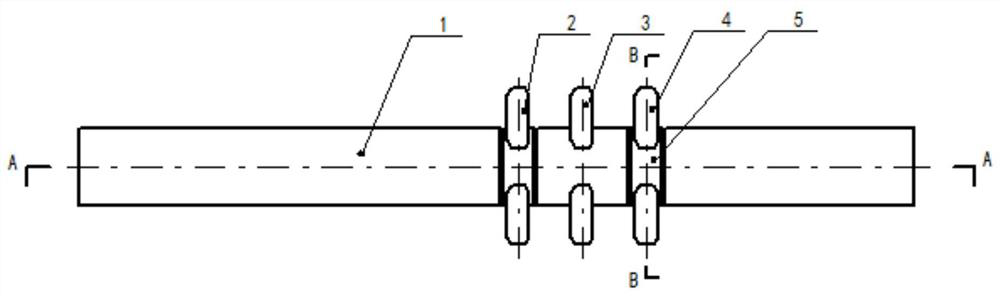
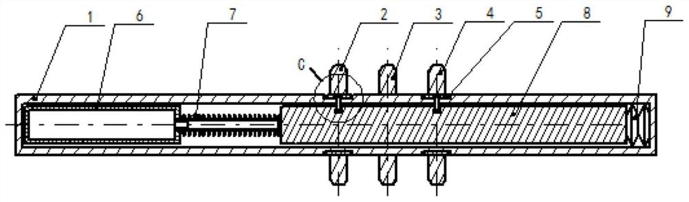
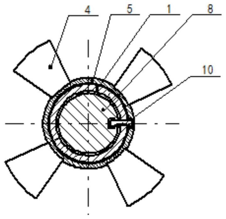
[0023] A temperature-controlled swimming type swirl gas well drainage plunger, including an outer cylinder 1, a liquid storage cylinder 6, a telescopic bellows 7, and a control rod 8. A control rod is installed in a coaxial gap on one side of the outer cylinder, and the control rod is connected to the A disc spring 9 is coaxially installed between the outer cylinders; a liquid storage cylinder is fixed on the other side of the outer cylinder, and a telescopic bellows is coaxially installed between the liquid storage cylinder and the control rod; A fixed vane 3 is installed coaxially and radially at the position of the control rod. An upper vane 2 and a lower vane 4 are respectively coaxially ins...


PUM


Abstract

The invention relates to a temperature-controlled swimming type swirling gas well drainage plunger. The plunger comprises an outer barrel, a liquid storage barrel, a telescopic corrugated pipe and a control rod; a control rod is installed on one side in the outer barrel through coaxial clearance, the liquid storage barrel is fixedly installed on the other side in the outer barrel, and the telescopic corrugated pipe is coaxially installed between the liquid storage barrel and the control rod; fixed blades are coaxially, radially and fixedly installed on the position, corresponding to the control rod, of the outer edge surface of the outer cylinder, upper blades and lower blades are coaxially installed on the portions, above and blow the fixed blades, of the outer barrel respectively, the structures of the upper blades and the lower blades are the same as the structures of the fixed blades, and the spacing is equal; the upper blades and the lower blades achieve coaxial opposite rotationon the outer barrel through axial displacement of the control rod by adopting a toggle mechanism, and then axial gaps between the fixed blades are closed or opened. Accordingly, automatic vertical swimming in a well can be achieved, by means of different characteristics of different well depth temperatures in a shaft, as long as the swimming range can cover the water ring range in a period of time, water in the well can be effectively discharged to the ground.

Description

technical field [0001] The invention belongs to the field of oil and gas well equipment, and relates to a device for discharging the water ring on the well wall of a gas well in a production well of a gas field, in particular to a temperature-controlled swimming swirl gas well drainage plunger. Background technique [0002] When the water produced by the gas well forms a water ring on the well wall, it is effective to add a cyclone below the position where the water ring is formed, and use the airflow to impact the water ring, turning the water into mist and following the airflow to reach the ground . Since the position of the water ring in the wellbore is affected by many factors, it will gradually move down with the influence of formation energy decline. This makes the cyclone need to follow the position of the water ring to effectively bring the water in the wellbore to the surface. [0003] At present, this kind of cyclone is fixed, and it needs to be re-fished manuall...

Claims


Application Information

Patent Timeline
Patent Type & Authority Patents(China)
IPC IPC(8): E21B43/00F04B47/12F04B53/14
CPCE21B43/121F04B47/12F04B53/14
Inventor 卢渊李沁伊向艺李成勇
Owner CHENGDU UNIVERSITY OF TECHNOLOGY
Why Eureka
Try Eureka