Coil-spring shaped bone external fixator
An external fixator and fixator technology, applied in the directions of external fixator, fixator, internal fixator, etc., can solve the problems of large trauma in bracket installation and complicated fixation operation, so as to reduce difficulty, save materials, and improve the convenience of installation Effect
- Summary
- Abstract
- Description
- Claims
- Application Information
AI Technical Summary
Problems solved by technology
Method used
Image

Examples
Embodiment 1
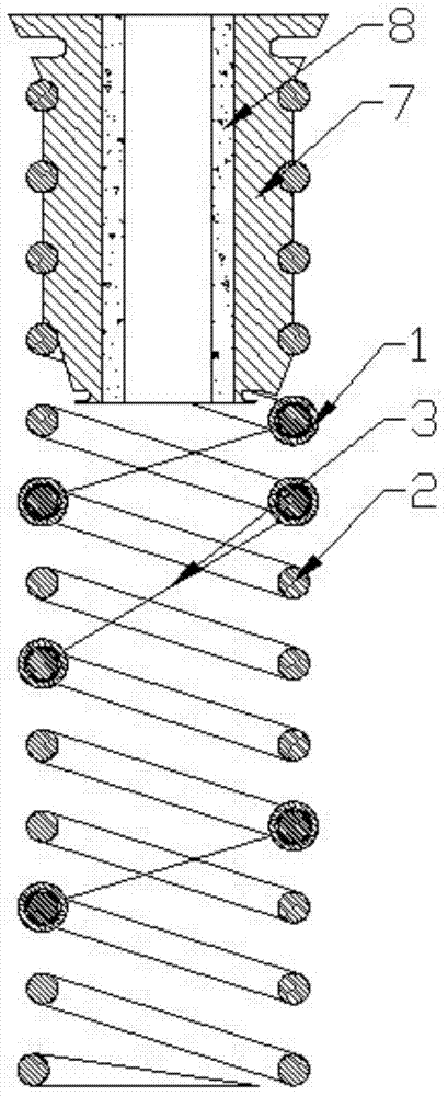
[0042] The external bone fixator mainly includes a number of longitudinal fixators and connecting brackets used to connect and fix each longitudinal fixator. At the same time, there are external fixators used to fix the limbs at both ends of the bracket. This product is mainly used for bone fixation. The longitudinal fixer is improved and the original steel nail fixation is cancelled;
[0043] Specific as figure 1 As shown, the longitudinal outer frame of this product is in the shape of a coil spring, and the bone surface fixation assembly is arranged inside the longitudinal outer frame. , the fixed block is fixed on the fixed outer frame 2, and the fixed cables 3 are positioned between the fixed blocks on the fixed outer frame 2 to form a support frame;
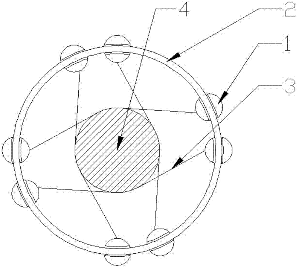
[0044] where fixed blocks (such as Figure 4 shown) includes a sliding hole 1-2 for fitting the fixed block 1 onto the fixed outer frame 2, a locking screw B is arranged on the inner wall of the sliding hole 1-2, and a A ...
Embodiment 2
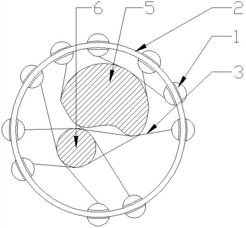
[0052] Such as image 3 As shown, it is a schematic diagram of the present invention when performing multiple bone fixation;
[0053] The external bone fixator mainly includes a number of longitudinal fixators and connecting brackets used to connect and fix each longitudinal fixator. At the same time, there are external fixators used to fix the limbs at both ends of the bracket. This product is mainly used for bone fixation. The longitudinal fixer is improved and the original steel nail fixation is cancelled;
[0054] Specific as figure 1 As shown, the longitudinal fixer in this product mainly includes several fixing blocks 1, and fixed cables 3 are arranged between the fixing blocks 1, and the fixing blocks are fixed on the fixing outer frame 2, and the fixing cables 3 The positioning of the fixed block on the fixed outer frame 2 forms a support frame;
[0055] where fixed blocks (such as Figure 4 shown) includes a sliding hole 1-2 for fitting the fixed block 1 onto the ...
Embodiment 3
[0060] At the same time, the present invention can cross-connect the fixed cables between the fixing blocks of different longitudinal anchors, for example, there are three longitudinal anchors for fixing, including longitudinal anchor A, longitudinal anchor B, and longitudinal anchor C , each vertical fixer includes 4 fixing blocks, among which the four fixing blocks of longitudinal fixer A are respectively marked as fixed block AI, fixed block AII, fixed block AIII, and fixed block AIV. The fixed block AI on A can be connected with the fixed block BII of the longitudinal fixer B through a fixed cable, and at the same time, the fixed block AII on the longitudinal fixer A and the fixed block CIV on the longitudinal fixer C are connected through a fixed cable, Two fixed cables form a supporting frame in contact with the bone surface.
PUM
 Abstract
Description
Claims
Application Information
 - R&D
- Intellectual Property
- Life Sciences
- Materials
- Tech Scout
- Unparalleled Data Quality
- Higher Quality Content
- 60% Fewer Hallucinations
Browse by: Latest US Patents, China's latest patents, Technical Efficacy Thesaurus, Application Domain, Technology Topic, Popular Technical Reports.
© 2025 PatSnap. All rights reserved.Legal|Privacy policy|Modern Slavery Act Transparency Statement|Sitemap|About US| Contact US: help@patsnap.com