Clamping device for nail driving

A clamping device and nail technology, which is applied in distribution devices, nail distributors, packaging, etc., can solve the problems of improper force control, low work efficiency, inconsistent nail depths, etc., and achieve the effect of consistent depth and convenient portability.

Inactive Publication Date: 2019-03-29
刘德塬
View PDF0 Cites 2 Cited by
  • Summary
  • Abstract
  • Description
  • Claims
  • Application Information

AI Technical Summary

Problems solved by technology

[0002] In building construction, it is often necessary to nail the boards together. The use of nails is essential, but the nails need to be supported by people to facilitate people to nail them into the boards. Usually, people hold the nails with their hands and then use a hammer to drive them into the boards. The nails are nailed into the board. Because the nails are small, people are easy to hit their hands when they swing the hammer, which will affect the follow-up work. And because the force is not properly controlled, the depth of the nails is inconsistent, so people will loosen the nails after a certain distance. Open your hands and swing the hammer slowly to hit the nails, so the nails are easy to be hammered and the work efficiency is low

Method used


Image

  • Clamping device for nail driving
  • Clamping device for nail driving

Examples


Embodiment 1

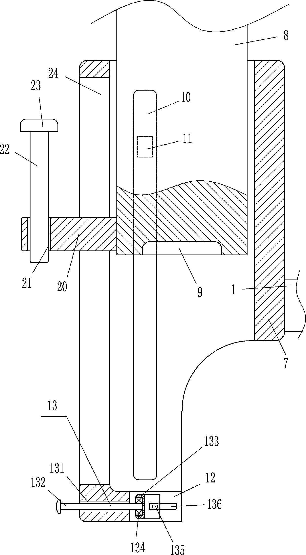
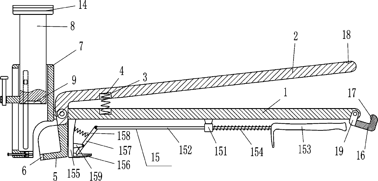
[0015] A clamping device for nailing, such as Figure 1-2 As shown, it includes a grip bar 1, a swing bar 2, a first spring 4, an L-shaped frame 5, a sleeve 7, a cylinder 8, a vertical slider 11, an adjustment device 13 and a rubber block 14, and the front side of the grip bar 1 The left side is hinged with a swing rod 2, the left side of the top of the swing rod 2 and the top left side of the grip rod 1 are provided with a first groove 3, and the bottom of the first groove 3 below is connected to the top of the first groove 3 above. The first spring 4, the L-shaped frame 5 that can be clamped by nails is installed on the bottom end of the swing rod 2, the L-shaped frame 5 is connected with the swing rod 2 through bolt connection, and the left side of the L-shaped frame 5 has a card slot 6 , the sleeve 7 is installed on the left end of the grip rod 1, the sleeve 7 is connected with the grip rod 1 by welding, the right side of the sleeve 7 is open, the sleeve 7 cooperates with ...

Embodiment 2

[0017] A clamping device for nailing, such as Figure 1-2 As shown, it includes a grip bar 1, a swing bar 2, a first spring 4, an L-shaped frame 5, a sleeve 7, a cylinder 8, a vertical slider 11, an adjustment device 13 and a rubber block 14, and the front side of the grip bar 1 The left side is hinged with a swing rod 2, the left side of the top of the swing rod 2 and the top left side of the grip rod 1 are provided with a first groove 3, and the bottom of the first groove 3 below is connected to the top of the first groove 3 above. The first spring 4, the L-shaped frame 5 that can clamp nails is installed on the bottom end of the swing rod 2, the left side of the L-shaped frame 5 has a card slot 6, the sleeve 7 is installed on the left end of the grip bar 1, and the sleeve 7 is on the right The side is open, and the sleeve 7 cooperates with the L-shaped frame 5. There is a through groove 12 on the right side of the lower part of the sleeve 7, and an adjustment device 13 is a...

Embodiment 3

[0020] A clamping device for nailing, such as Figure 1-2 As shown, it includes a grip bar 1, a swing bar 2, a first spring 4, an L-shaped frame 5, a sleeve 7, a cylinder 8, a vertical slider 11, an adjustment device 13 and a rubber block 14, and the front side of the grip bar 1 The left side is hinged with a swing rod 2, the left side of the top of the swing rod 2 and the top left side of the grip rod 1 are provided with a first groove 3, and the bottom of the first groove 3 below is connected to the top of the first groove 3 above. The first spring 4, the L-shaped frame 5 that can clamp nails is installed on the bottom end of the swing rod 2, the left side of the L-shaped frame 5 has a card slot 6, the sleeve 7 is installed on the left end of the grip bar 1, and the sleeve 7 is on the right The side is open, and the sleeve 7 cooperates with the L-shaped frame 5. There is a through groove 12 on the right side of the lower part of the sleeve 7, and an adjustment device 13 is a...


PUM


Abstract

The invention relates to a clamping device, in particular to a clamping device for nail driving. The technical problem to be solved is to provide the clamping device for nail driving which is characterized in that a nail can be clamped, so that people can drive in the nail conveniently, do not need to hold the nail by hands, and can be prevented from knocked injury, in addition, the drive-in depthof one nail can be consistent with that of another nail. The technical scheme is to provide the clamping device for the nail driving. The device comprises a holding rod, a swing rod, a first spring,an L-shaped frame, a sleeve, a cylinder body, a vertical sliding block and the like; the swing rod is hinged to the left side of the front side face of the holding rod, first grooves are formed in theleft side of the inner top of the swing rod and the left side of the top of the holding rod, and the first spring is connected between the bottom of the first groove at the lower portion and the topof the first groove at the upper portion. According to the device, the nail can be clamped by the cooperation between an arc-shaped plate and a clamping groove, the nail can be in contact with the cylinder body, then the cylinder body is knocked to move downwards, thus the nail can move downwards to be driven into a wooded board; the nail is not required to be held by hands, so that the hands areprevented from knocked injury; and by means of a prying device, people can conveniently pull the nail out of the wooden board.

Description

technical field [0001] The invention relates to a clamping device, in particular to a clamping device for nailing. Background technique [0002] In building construction, it is often necessary to nail the boards together. The use of nails is essential, but the nails need to be supported by people to facilitate people to nail them into the boards. Usually, people hold the nails with their hands and then use a hammer to drive them into the boards. The nails are nailed into the board. Because the nails are small, people are easy to hit their hands when they swing the hammer, which will affect the follow-up work. And because the force is not properly controlled, the depth of the nails is inconsistent, so people will loosen the nails after a certain distance. Open your hands, and slowly swing the hammer to hit the nails, so the nails are easily bent by the hammer, and the work efficiency is low. Contents of the invention [0003] In order to overcome the shortcoming that due t...

Claims


Application Information

Patent Timeline
Patent Type & Authority Applications(China)
IPC IPC(8): B25C3/00
CPCB25C3/00B25C3/006
Inventor 刘德塬
Owner 刘德塬
Why Eureka
Try Eureka