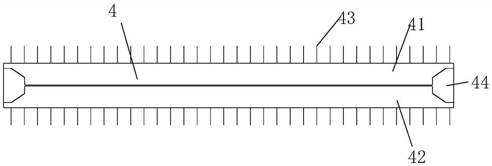
Anti-robbing baton
A baton and column technology, applied to batons, weapons without explosives, etc., can solve the problems of not being able to be taken away, not being able to achieve law enforcement, being taken away, etc., and achieve the effect of novel conception, simple trigger mechanism, and ingenious design
- Summary
- Abstract
- Description
- Claims
- Application Information
AI Technical Summary
Problems solved by technology
Method used
Image
Examples
Embodiment 1
[0036] Such as Figure 1-Figure 9 As shown, an anti-robbing baton comprises:
[0037] handle 1,
[0038] The stick body 2, the stick body 2 is a hollow structure, and the stick body 2 is fixed on the front end of the handle 1, and the end of the stick body 2 close to the handle 1 is provided with a movable inner cone 5, and the corresponding movable inner cone 5 on the stick body 2 There is a movable hole 25 at the position, and the other end of the stick body 2 is threadedly connected with the limiter 6, and the position of the limiter 6 on the surface of the stick body 2 is oppositely provided with a casing limit groove 24, and the outer wall of the stick body 2 is symmetrical. Needle outlet holes 23 are provided;
[0039] The movable inner cone 5 includes a cylinder 51 which is movably arranged in the stick body 2, a frustum 52 arranged at the front end of the cylinder 51, and the frustum 52 is placed inside the front spring 53 arranged at the front end of the cylinder 51...
Embodiment 2
[0051] Such as Figure 10 As shown, on the basis of Example 1, the upper limit cylinder 411 and the lower limit cylinder 421 are removed, and the accommodating cavity 44 is set in a conical shape, as another embodiment of fixing the upper stick body 41 and the lower stick body 42, A pair of fixing holes 46 are arranged oppositely on the upper stick body 41 and the lower stick body 42 , and a first connecting spring 461 or a rubber band is arranged in the fixing holes 46 for fixing the upper stick body 41 and the lower stick body 42 .
Embodiment 3
[0053] Such as Figure 11 As shown, on the basis of Example 1, the upper limit cylinder 411 and the lower limit cylinder 421 are removed, and the accommodating cavity 44 is set in a conical shape, as another embodiment of fixing the upper stick body 41 and the lower stick body 42, The outer walls of the upper stick body 41 and the lower stick body 42 are oppositely provided with fixing grooves 47 , and the fixing grooves 47 are provided with a second connecting spring 471 or a rubber band for fixing the upper stick body 41 and the lower stick body 42 .
PUM
 Abstract
Description
Claims
Application Information
 - R&D
- Intellectual Property
- Life Sciences
- Materials
- Tech Scout
- Unparalleled Data Quality
- Higher Quality Content
- 60% Fewer Hallucinations
Browse by: Latest US Patents, China's latest patents, Technical Efficacy Thesaurus, Application Domain, Technology Topic, Popular Technical Reports.
© 2025 PatSnap. All rights reserved.Legal|Privacy policy|Modern Slavery Act Transparency Statement|Sitemap|About US| Contact US: help@patsnap.com


