
Anti-siphon valve and sanitary ware using same

An anti-siphon and valve shell technology, applied in the field of sanitary ware, can solve the problems of insufficient elasticity, easy aging, closed slits, etc., and achieve the effects of average deformation, not easy to fatigue, and long service life

Active Publication Date: 2019-04-05
XIAMEN KEMU INTELLIGENT TECH
View PDF8 Cites 5 Cited by
  • Summary
  • Abstract
  • Description
  • Claims
  • Application Information

AI Technical Summary

Problems solved by technology

Since the deformed part of this valve is made of soft material, it is easy to age after long-term use and cause insufficient elasticity, so that the slit at the end of the deformed part will form a constant opening. When the water is turned off, the reverse pressure cannot directly close the slit , it may even cause the middle part of the deformation part to roll inward, so that the effect of non-return cannot be achieved

Method used


Image

  • Anti-siphon valve and sanitary ware using same
  • Anti-siphon valve and sanitary ware using same
  • Anti-siphon valve and sanitary ware using same

Examples


Embodiment 1

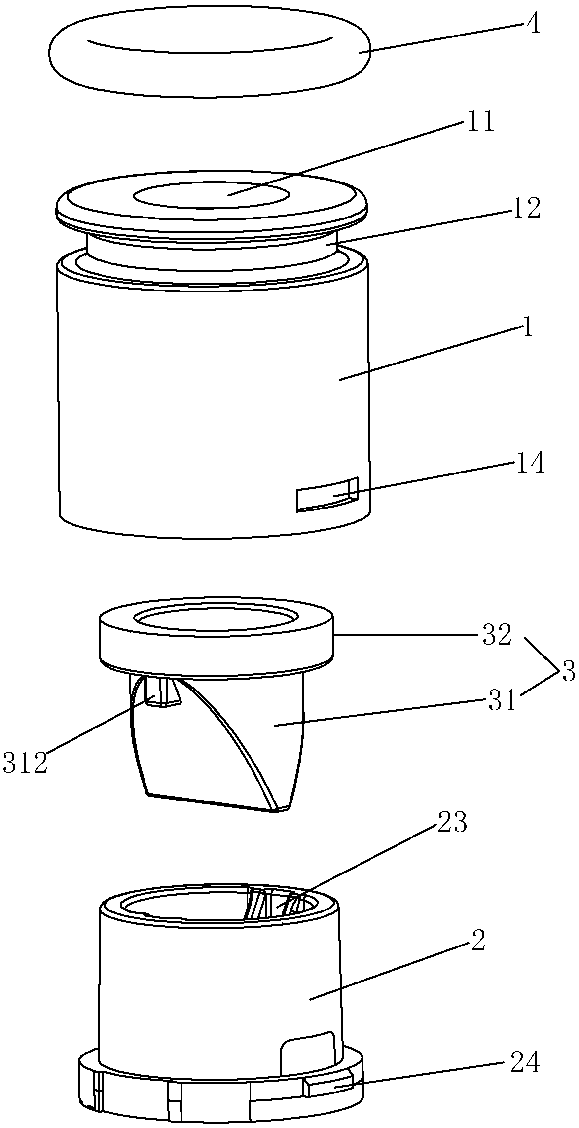
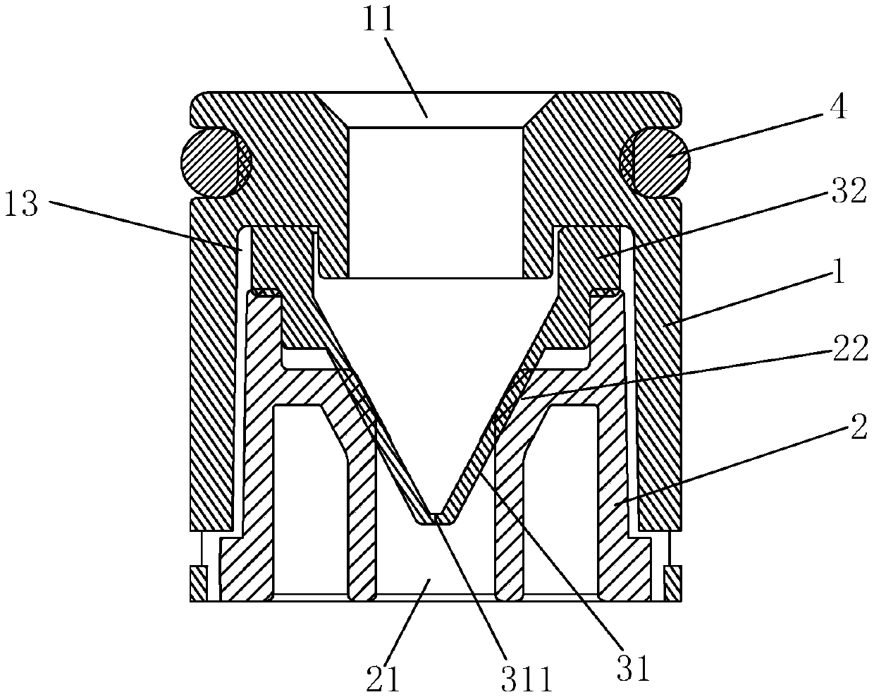
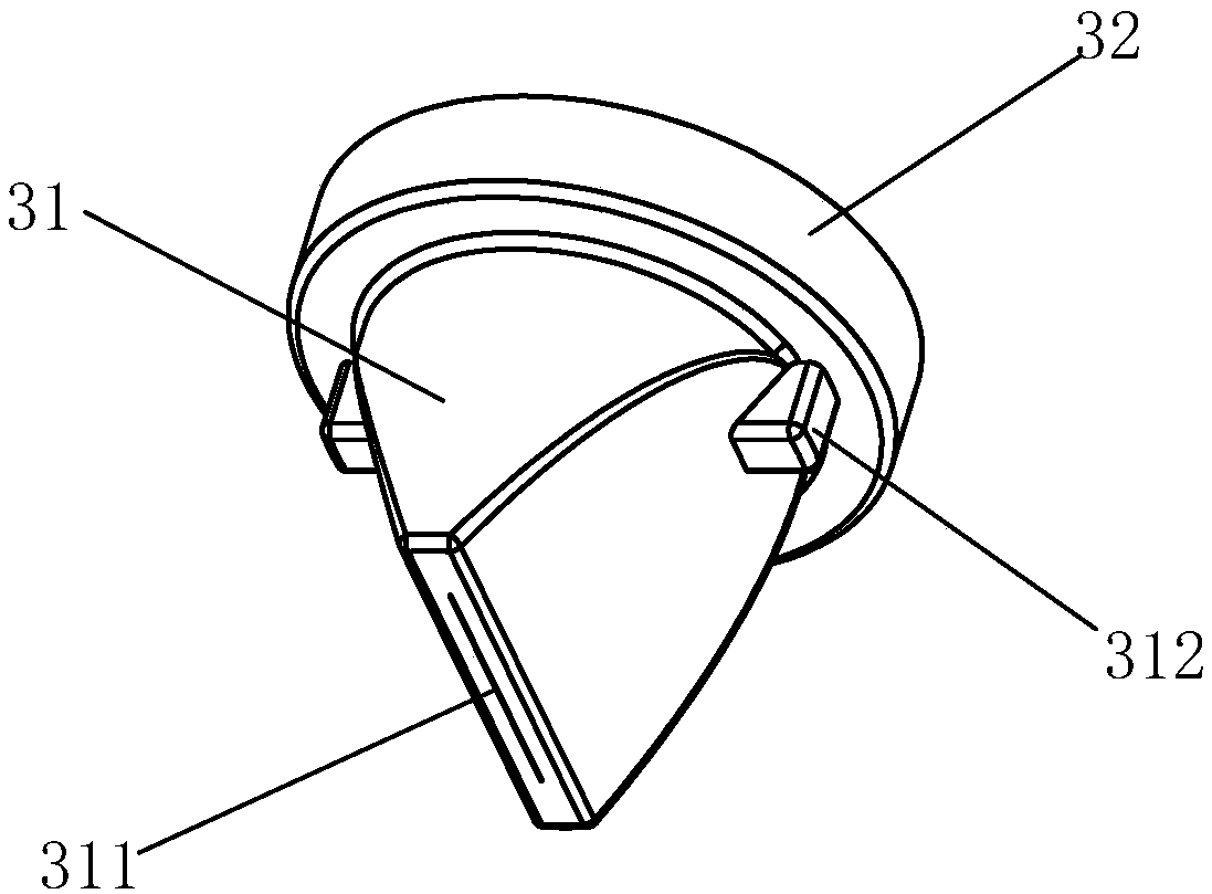
[0033] See Figure 1-Figure 5 As shown, an anti-siphon valve of the present invention includes a valve housing and a valve core 3. The two ends of the valve housing are respectively provided with a fluid inlet 11 and a fluid outlet 21. The valve core 3 is arranged in the valve cavity of the valve housing. The valve core 3 has a wedge-shaped deformation portion 31 facing the fluid outlet 21, and the tail end of the deformation portion 31 is provided with a slit 311 that can be opened and closed; the valve cavity of the valve housing is provided with two pre-compression structures, The two pre-compression structures pre-compress the outer surfaces of the two inclined walls of the deformation part 31 one by one, so that the deformation part 311 is deformed. The valve housing specifically includes an upper housing 1 provided with the fluid inlet 11 and a lower housing 2 provided with the fluid outlet 21 , the two are connected and matched to form the valve chamber. The pre-compre...

Embodiment 2

[0045] See Figure 8-Figure 13 As shown, an anti-siphon valve of the present invention differs from Embodiment 1 in that: the tail end of the deformation part 31 is provided with an extension part outwards, and the extension part includes two thin pieces 33, and the two thin pieces 33 are opposite to each other. Set and be located on both sides of the width direction of the slit, and the distance between the tail ends of the two sheets 33 is smaller than the width of the slit (in addition, the distance between the two sheets 33 can also be adapted to the width of the slit). The two sides of the two sheets 33 are connected one by one, but it is not limited thereto, and the two sheets 33 can also be separated from each other.

[0046] In this embodiment, the extension is in the shape of an inverted T (in addition, the extension can also be in the shape of an I), the valve housing is provided with two ribs 25, and the two ribs 25 are locked one by one. Inwardly recessed parts on...


PUM


Abstract

The invention discloses an anti-siphon valve and a sanitary ware using the same. The valve includes a valve shell and a valve core. A fluid inlet and a fluid outlet are separately formed in the two ends of the valve shell. The valve core is disposed in a valve cavity of the valve shell, the valve core is provided with a wedge-shaped deformation part facing the fluid outlet, and a slit which can beopened and closed is formed in the tail end of the deformation part. The valve cavity of the valve shell is internally provided with two pre-compacting structures, the two pre-compacting structures pre-compress on the outer side surfaces of two inclined walls of the deformation part one by one. The pre-compacting structures are capable of squeezing the deformation part, so that the deformation part is more easily reset to the state of slit closing after the slit is opened by deformation, the deformation portion is less prone to being fatigued and aged, a longer service life is achieved, and the non-return effect of the valve is better.

Description

technical field [0001] The invention relates to a valve, in particular to a valve capable of preventing siphon and sanitary ware using the valve. Background technique [0002] A valve with a wedge-shaped deformation portion in the prior art is favored because of its anti-siphon function, and is widely used. When the valve has no internal pressure, the slit at the tail end of the wedge-shaped deformation part is closed under the elastic action of the deformation part itself, and as the internal pressure gradually increases, the slit opens to discharge the fluid; when the valve is When negative pressure appears on the side where the fluid inlet is located, the deformed part is deformed by the atmospheric pressure on the side where the fluid outlet is located to close the slit, thereby realizing the anti-siphon function. Since the deformed part of this valve is made of soft material, it is easy to age after long-term use and cause insufficient elasticity, so that the slit at t...

Claims


Application Information

Patent Timeline
Patent Type & Authority Applications(China)
IPC IPC(8): F16K15/14E03D11/18E03D11/13
CPCE03D11/13E03D11/18F16K15/147
Inventor 林孝发林孝山林山吴金华
Owner XIAMEN KEMU INTELLIGENT TECH
Learn More