
Bicycle shaft multi-stage transmission internal speed variator

A speed change device, bicycle technology, applied in the direction of wheel transmission, vehicle gearbox, vehicle parts, etc., can solve problems such as off-chain, poor transmission stability, complex structure, etc.

Pending Publication Date: 2019-04-12
SHANGHAI SECOND POLYTECHNIC UNIVERSITY
View PDF7 Cites 3 Cited by
  • Summary
  • Abstract
  • Description
  • Claims
  • Application Information

AI Technical Summary

Problems solved by technology

The traditional bicycle relies on the wheel disc installed on the central shaft to drive the flywheel installed on the rear axle of the bicycle through the chain, and then drives the rear wheel of the bicycle to rotate through the flywheel. However, due to the structural problems of the chain transmission system itself, the chain transmission is Additional dynamic loads will be generated during work, the transmission stability is poor, and the torque that can be tolerated is small. The chain is easy to wear and stretch. During riding, the chain often falls off and breaks, and the chain and flywheel clamp clothing. Lubricating oil stains underwear, etc.
[0003] Most of the shaft drive bicycles currently on the market have complex structures, high production costs, and difficult maintenance, so the market share is low, and shaft drive bicycles without speed-changing functions are difficult to adapt to various terrains and road conditions

Method used


Image

  • Bicycle shaft multi-stage transmission internal speed variator
  • Bicycle shaft multi-stage transmission internal speed variator
  • Bicycle shaft multi-stage transmission internal speed variator

Examples


Embodiment Construction

[0056] Specific embodiments of the present invention will be further described below in conjunction with the accompanying drawings.

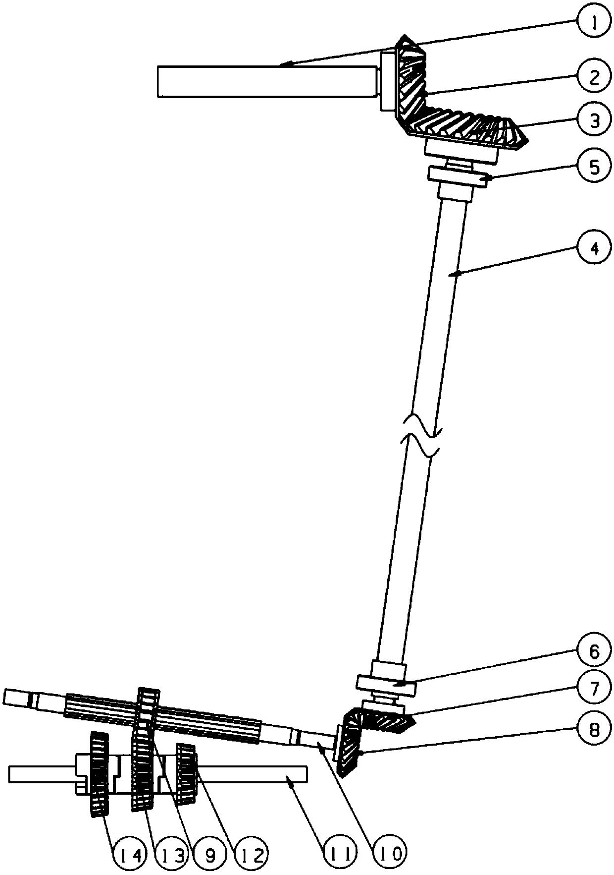
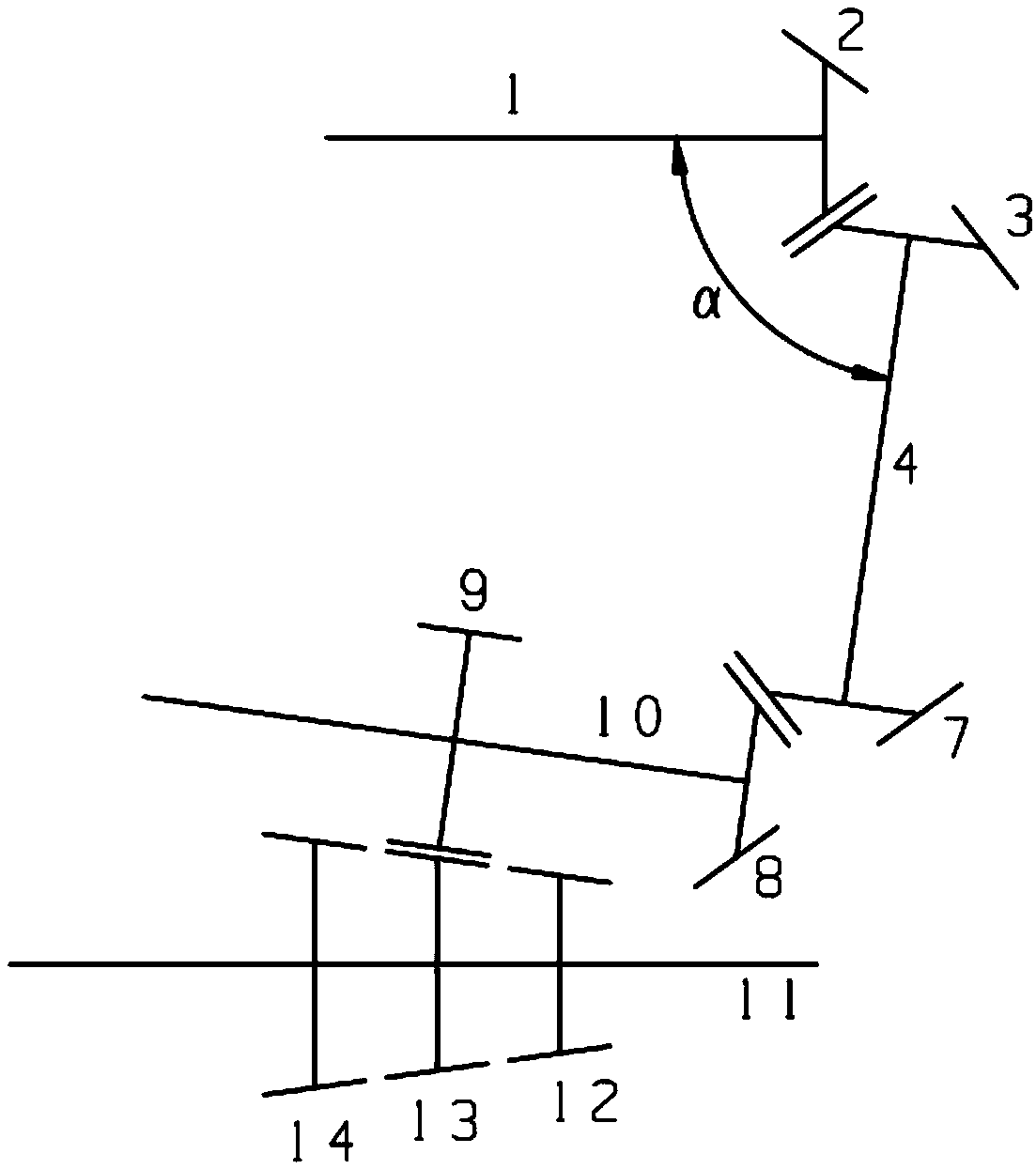
[0057] Such as figure 1 and combine figure 2 As shown, an embodiment of a bicycle shaft transmission multi-stage internal speed change device is disclosed. Two bevel gears 13 and the third bevel gear 12.

[0058] One end of the spline shaft 10 is connected to the power source of the bicycle through transmission, and the specific spline shaft 10 is sequentially connected to the power source of the bicycle (ie, the bicycle pedal) through the transmission shaft 4 and the central shaft 1 of the bicycle.

[0059]One end of the spline shaft 10 in drive connection with the transmission shaft 4 is provided with a first rear helical bevel gear 8 , and the transmission shaft 4 is correspondingly provided with a second rear helical bevel gear 7 meshing with the first rear helical bevel gear 8 . Wherein the second rear spiral bevel gear 7 is a driving g...


PUM


Abstract

The invention discloses a bicycle shaft multi-stage transmission internal speed variator. The speed variator comprises a spline shaft, a variable speed cylindrical gear, a first bevel gear, a second bevel gear and a third bevel gear, wherein one end of the spline shaft is in transmission connection with a bicycle power source; the spline shaft is coaxially sleeved with the variable speed cylindrical gear, and the variable speed cylindrical gear is capable of sliding axially along the spline shaft; a rear axle of a bicycle is coaxially sleeved with the first bevel gear, the second bevel gear and the third bevel gear which are sequentially arranged; the variable speed cylindrical gear is driven by an adjusting device to slide among and be meshed with the first bevel gear, the second bevel gear and the third bevel gear; the number of gears of the first bevel gear is greater than the number of gears of the second bevel gear, and the number of gears of the second bevel gear is greater thanthe number of gears of the third bevel gear. According to the speed variator provided by the invention, the variable speed is realized by sliding of the variable speed cylindrical gear among the low,medium and high speed bevel gears on the rear axle of the bicycle and the switched meshing between the variable speed cylindrical gear and the low, medium and high speed bevel gears, and the speed variator is compact in structure, few in parts, easy to maintain and long in maintenance period.

Description

technical field [0001] The invention relates to bicycle parts, in particular to a bicycle shaft transmission multi-stage internal speed change device. Background technique [0002] As one of the most commonly used means of transportation, bicycle can not only replace walking for fitness, but also avoid urban traffic congestion, so it is deeply favored by people. The traditional bicycle relies on the wheel disc installed on the central shaft to drive the flywheel installed on the rear axle of the bicycle through the chain, and then drives the rear wheel of the bicycle to rotate through the flywheel. However, due to the structural problems of the chain transmission system itself, the chain transmission is Additional dynamic loads will be generated during work, the transmission stability is poor, and the torque that can be tolerated is small. The chain is easy to wear and stretch. During riding, the chain often falls off and breaks, and the chain and flywheel clamp clothing. L...

Claims


Application Information

Patent Timeline
Patent Type & Authority Applications(China)
IPC IPC(8): B62M11/10
CPCB62M11/10
Inventor 崔立姜昊王包寿李帅康聂辰佳张洪生何亚飞
Owner SHANGHAI SECOND POLYTECHNIC UNIVERSITY
Learn More