Fixing method of superhard tool and hard contact

A technology of hard contacts and superhard tools, which is applied in the direction of manufacturing tools, striking tools, light impact tools, etc., and can solve the problems of hard contacts being damaged, falling off, and superhard contacts falling off, etc.

Active Publication Date: 2015-08-12
TRYTEC
View PDF5 Cites 0 Cited by
  • Summary
  • Abstract
  • Description
  • Claims
  • Application Information

AI Technical Summary

Problems solved by technology

[0003] However, when the object to be heated is high temperature, the tool itself that fixes the hard contact by the above-mentioned brazing or caulking method will be heated to a high temperature. Problems such as damaged or falling off
For example, the milling hole of the melting furnace is closed again at the end of the milling of the molten milling iron and moved to the next melting operation. (In order to make the front end of the mud gun for sealing (mud gun) close contact with the peripheral part of the milling hole opening, it needs to be flattened.) Since the furnace wall is at a high temperature, if the hard contact is used The drill bit after brazing or the drill bit after sintering will have the problem that the superhard contact will fall off immediately

Method used


Image

  • Fixing method of superhard tool and hard contact
  • Fixing method of superhard tool and hard contact
  • Fixing method of superhard tool and hard contact

Examples


Embodiment 1

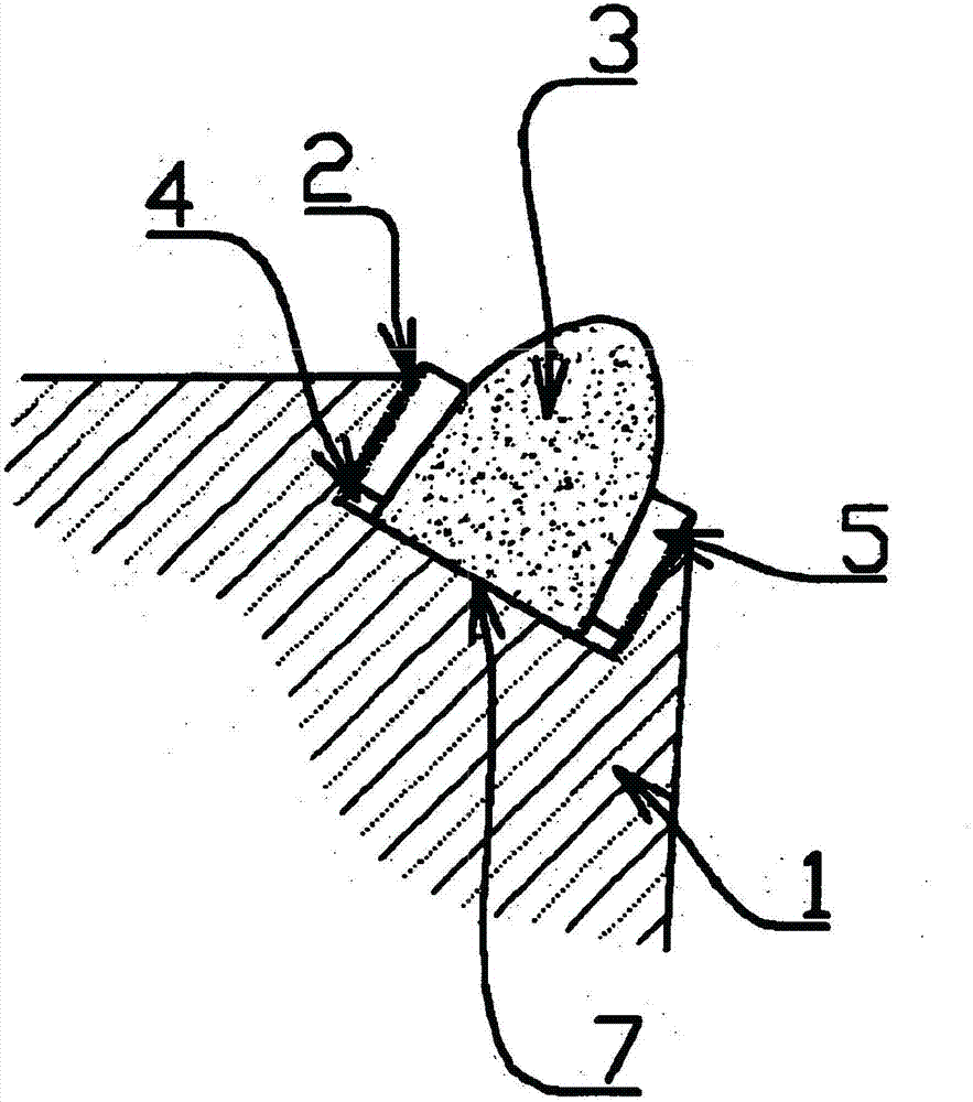
[0026] figure 1 The superhard tool of the present invention is shown as an example, in which a base portion of a hard contact 3 (in this case, a superhard contact) is fitted into a contact hole 2 provided in the head portion of a steel base 1 . The bottom surface of the contact 3 is in close contact with the bottom surface 7 of the contact hole 2 .

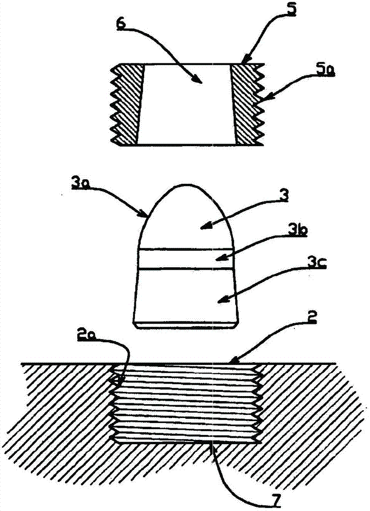
[0027] Such as figure 2 As shown, the hard contact 3 is composed of a head portion 3a, a body portion 3b, and a base portion 3c. The head portion 3a is formed in a substantially cannonball shape with a small diameter at the front end and a large diameter at the body portion side. The main body 3b has a cylindrical shape with the same diameter, and the base 3c is formed as an inclined surface having a conical cross section with a smaller diameter on the main body side and a gradually larger diameter on the base side.

[0028] The inner diameter of the contact hole 2 of the base body 1 is larger than the outer diameter of the lar...

Embodiment 2

[0034] then, Figure 7 , Figure 8 It is a figure which shows the embodiment slightly different from the above-mentioned, and in this Example, the base part of the hard contact 3 is integrally formed with the flange 31. The outer diameter of this flange 31 is substantially the same as the inner diameter of the contact hole 2, and its height is several millimeters, on which a pressing ring 5 is screwed, and the lower surface of the pressing ring 5 is in close contact with the upper surface of the above-mentioned flange 31. In this way, since the flange 31 integrated with the hard contact 3 is pressed by the pressing ring 5, the fixing of the hard contact 3 can be made more reliable.

Embodiment 3

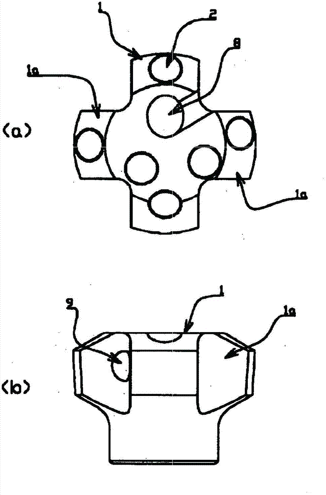
[0036] then, Figure 9 , Figure 10It is a figure which shows the reference example different from the above, and in this example, the male thread 14 is provided directly in the outer peripheral part of the base part of the hard contact 13. As shown in FIG. The hard contact 13 is directly screwed into the contact hole 2 engraved with a female thread. That is, the hard contact 13 is screwed directly to the base 1 . While it is often possible to thread the part to the base material, hard contacts are generally brittle and cannot be secured by threads. However, since the tools used for the opening of the milling hole are mostly discarded after being used once, this threaded fastening method can be used. Although it is also possible to form a male thread on the hard contact itself as described above, it is generally difficult to form a threaded portion on such a hard contact. It is ideal for practical use.

[0037] As explained above, according to the method for fixing hard c...


PUM


Abstract

Provided are a tool wherein a super-hard tip, such as a cemented carbide tip, is fixed to a steel base, and which is suitable for use primarily for purposes such as opening a taphole; and a practical method of fixing the super-hard tip in the case of said tool. Said tool is a cemented carbide tool which is characterized in that a super-hard tip is inserted into an internally threaded tip hole formed in the steel base, and that a hold-down ring which is provided with a male thread around the external periphery thereof and is capable of being threadably engaged with said tip hole, is threadably installed in the tip hole in such a way as to be fitted over the super-hard tip, resulting in the super-hard tip being pressed and fixed. It is desirable that the external peripheral surface of the super-hard tip be formed as a conical inclined surface wherein the diameter in the upper portion (tip portion) is smaller and the diameter in the lower portion (base portion) is larger, and that the internal peripheral surface of the hold-down ring be formed as a trumpet-shaped inclined surface which closely mates with the conical inclined surface of the super-hard tip.

Description

technical field [0001] The present invention relates to a tool (hereinafter referred to as "superhard tool") that uses a contact (hereinafter referred to as "hard contact") mounted with cemented carbide such as a drill bit, an impact tool, or ceramics, etc. The fixing method of the hard contact. Background technique [0002] Hole cutting drills or surface finishing tools used in masonry are in many cases embedded with hard contacts (usually superhard contacts) in a steel matrix. As the installation method of the above-mentioned hard contact, the most common method is to drill a contact hole to fit the hard contact on the substrate, and to fit the hard contact to the contact hole and perform brazing. Or burning embedded method. [0003] However, when the object to be heated is high temperature, the tool itself that fixes the hard contact by the above-mentioned brazing or caulking method will be heated to a high temperature. Damaged or falling off such a problem. For examp...

Claims


Application Information

Patent Timeline
Patent Type & Authority Patents(China)
IPC IPC(8): E21B10/52B25D17/02B28D1/14
CPCB28D1/14E21B10/62C21B7/12F27D3/1527E21B10/56E21B10/58
Inventor 竹崎博
Owner TRYTEC
Why Eureka
Try Eureka