Three-arc harmonic gear slotting cutter and tooth profile design method thereof

A technology of harmonic gear and gear shaping cutter, which is applied in the field of harmonic reducer gear processing tools, can solve the problem of not considering the tangential displacement of the flexspline and the movement of the symmetry line of the flexspline tooth, so as to improve the bearing capacity and transmission accuracy , uniform distribution, and the effect of increasing the number of meshing teeth

CN109630652AActive Publication Date: 2019-04-16SICHUAN UNIV
7 Cites 8 Cited by

Patent Information

Authority / Receiving Office
CN · China
Current Assignee / Owner
Publication Date
2019-04-16

Smart Images

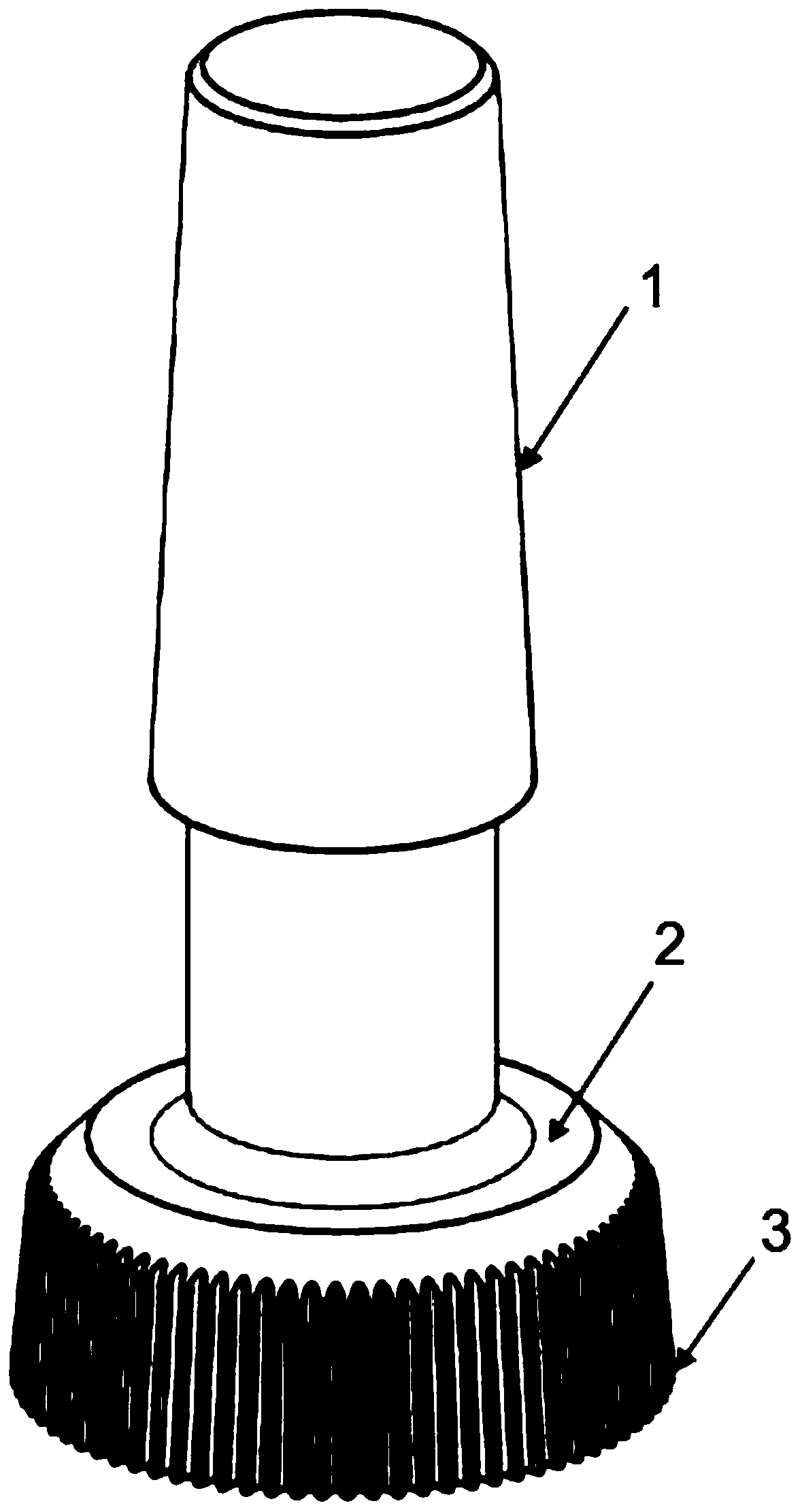
  • Figure 1
    Figure 1
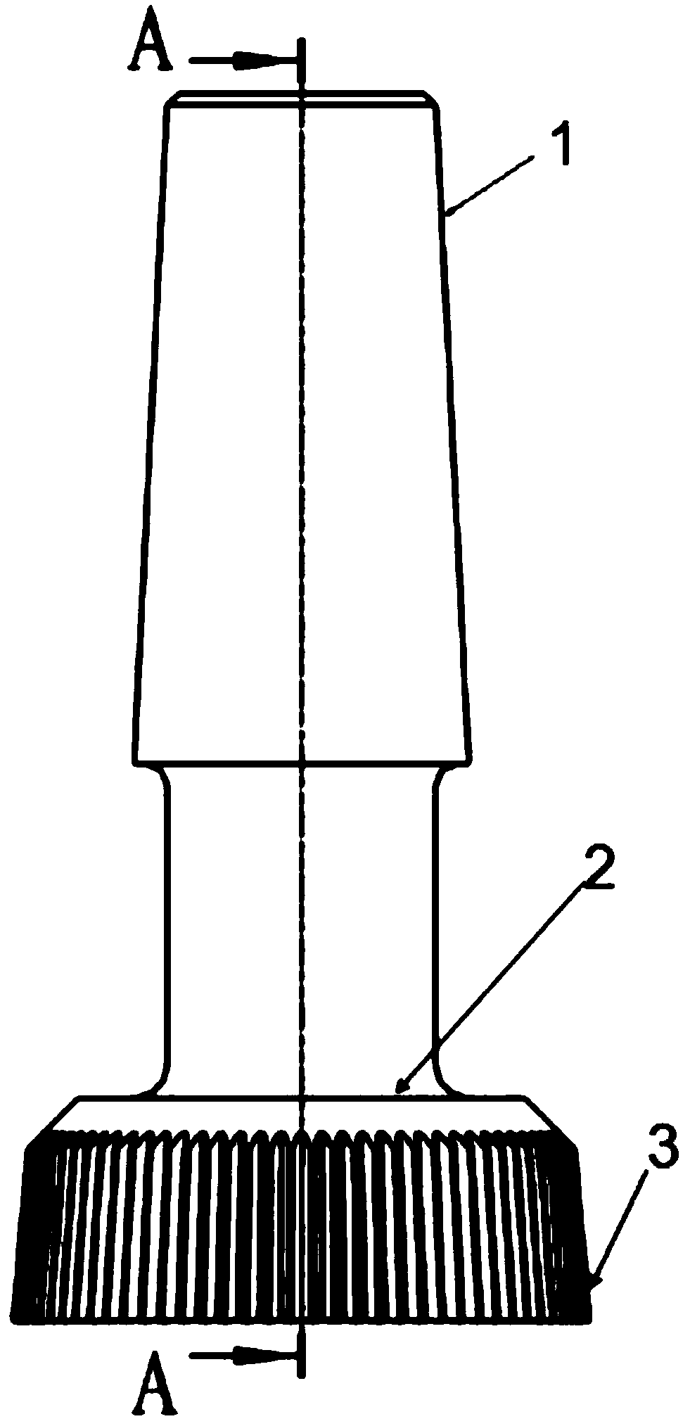
  • Figure 2
    Figure 2
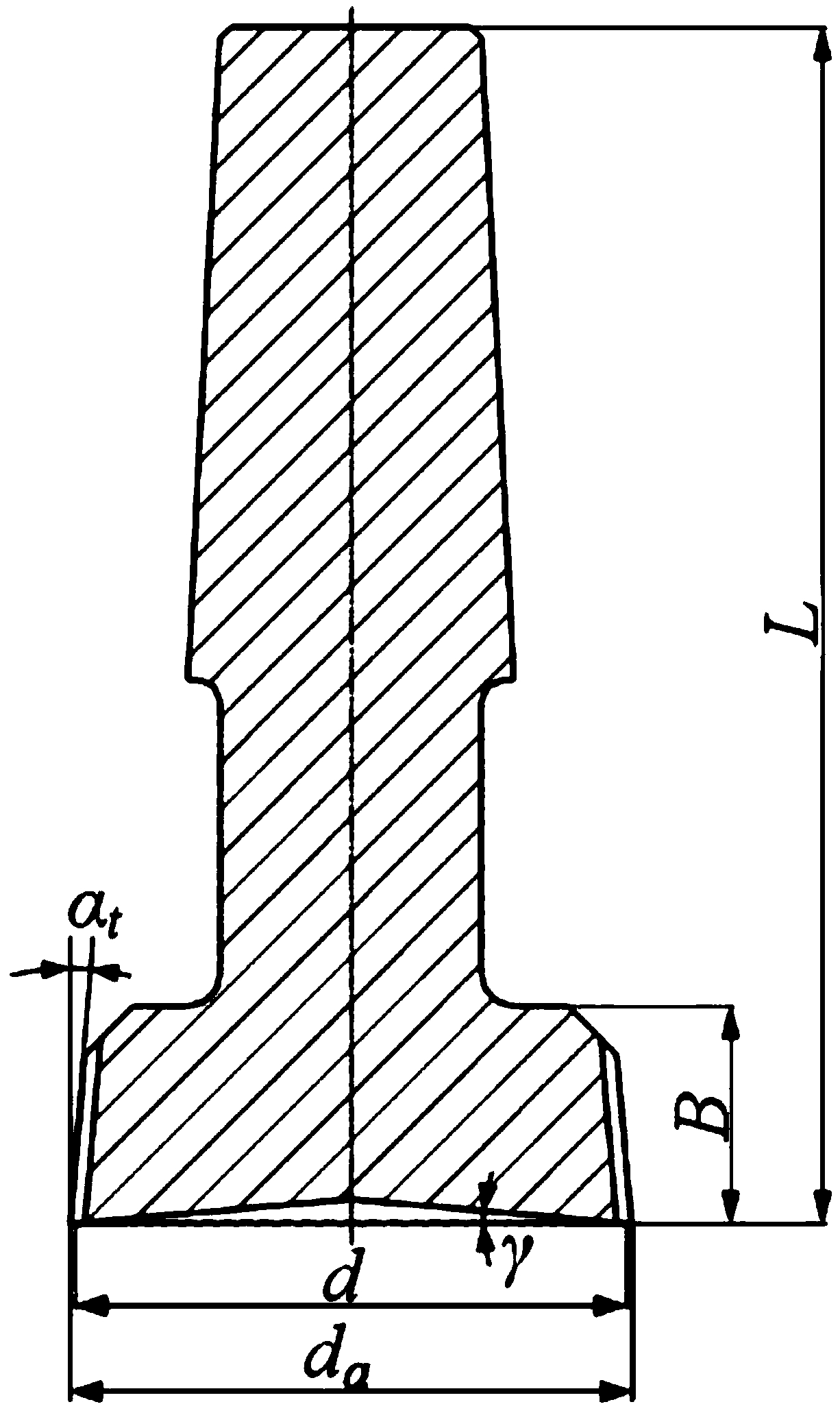
  • Figure 3
    Figure 3
Patent Text Reader

Abstract

The invention discloses a three-arc harmonic gear slotting cutter, and belongs to the technical field of harmonic speed reducer gear machining cutters. A basic tooth profile of cutter teeth is composed of three arc sections which are sequentially tangent. The radius of the upper arc section is rho 1, the radius of the middle arc section is rho 2, and the radius of the lower arc section is rho 3. The invention further discloses a tooth profile design method of the three-arc harmonic gear slotting cutter. Through the tooth profile design method, a flexible gear three-arc tooth profile and a rigid gear three-arc tooth profile which meet the conditions are designed; and on the basis of the obtained rigid gear three-arc tooth profile, the gear meshing kinematics method is adopted, and an A section theoretical conjugate tooth profile, a B section theoretical conjugate tooth profile and a C section theoretical conjugate tooth profile are obtained. Arc fitting is adopted, and the upper arc section Ac1, the lower arc section Ac3 and related parameters of the upper arc section Ac1 and the lower arc section Ac3 are obtained. Through the plane analytic geometry method, the middle arc section Ac2 and related parameters of the middle arc section Ac2 are obtained. Finally, according to the machined harmonic gear technology requirements, auxiliary parameters are determined, and accordingly thepurpose of machining of a work tooth profile of a three-arc harmonic gear is achieved.
Need to check novelty before this filing date? Find Prior Art

Description

technical field

[0001] The invention belongs to the technical field of gear processing tools for harmonic reducers, and in particular relates to a three-arc harmonic gear shaper cutter and a tooth profile design method thereof. Background technique

[0002] Harmonic gear transmission is a transmission device in which the wave generator acts to control the elastic deformation of the flexspline to transmit force and motion. It has a series of advantages such as large transmission ratio, light weight, small size, large number of meshing tooth pairs, and high transmission precision. It has become the core key component of the equipment transmission system in the fields of industrial robots, aerospace, machine tools and medical equipment.

[0003] When the American scholar MUSSER obtained the patent of the harmonic gear transmission in 1959, he adopted a linear tooth shape with a large pressure angle. Although this tooth shape can meet the requirements of a fixed transmission rat...

Examples

Embodiment Construction

[0050] In order to make the purpose, technical solutions and advantages of the embodiments of the present invention clearer, the technical solutions in the embodiments of the present invention will be clearly and completely described below in conjunction with the drawings in the embodiments of the present invention. Obviously, the described embodiments It is a part of embodiments of the present invention, but not all embodiments. The components of the embodiments of the invention generally described and illustrated in the figures herein may be arranged and designed in a variety of different configurations.

[0051] Accordingly, the following detailed description of the embodiments of the invention provided in the accompanying drawings is not intended to limit the scope of the claimed invention, but merely represents selected embodiments of the invention. Based on the embodiments of the present invention, all other embodiments obtained by persons of ordinary skill in the art wi...