
Cable bridge

A cable tray, together technology, used in electrical components, springs/shock absorbers, vibration suppression adjustment and other directions, can solve problems such as cable falling off, and achieve the effect of avoiding loosening and improving installation stability.

Active Publication Date: 2019-04-16
WUHAN MARINE MACHINERY PLANT
View PDF8 Cites 4 Cited by
  • Summary
  • Abstract
  • Description
  • Claims
  • Application Information

AI Technical Summary

Problems solved by technology

[0005] When the cable flows a large current, under the action of electromagnetic induction, the cable will vibrate relative to the crosspiece, and since the cable and the crosspiece are only fixedly connected by a cable tie, under long-term vibration, once the cable tie If there is looseness, there will be a risk of the cable falling off

Method used


Image

  • Cable bridge
  • Cable bridge
  • Cable bridge

Examples


Embodiment Construction

[0029] In order to make the objectives, technical solutions and advantages of the present invention clearer, the embodiments of the present invention will be described in further detail below in conjunction with the accompanying drawings.

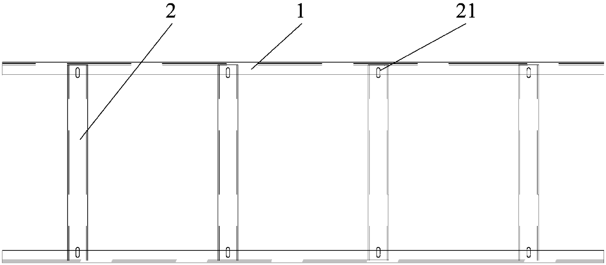
[0030] The embodiment of the present invention provides a cable tray, such as figure 1 As shown, the cable tray includes: two ladder sides 1 and a plurality of rungs 2, the two ladder sides 1 are arranged parallel to each other, one end of each rung 2 is fixedly installed on one ladder edge 1, and the other rungs 2 One end is fixed on the other side 1 of the ladder, and the rungs 2 are arranged at intervals along the length of the side 1 of the ladder.

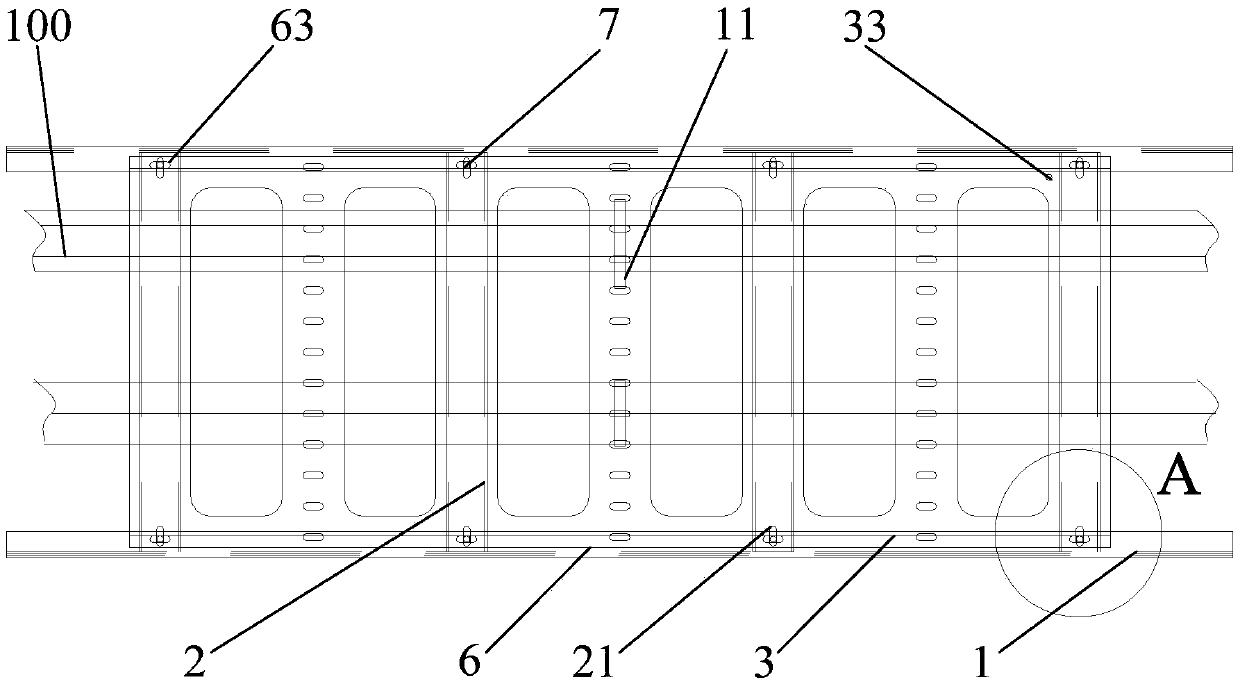
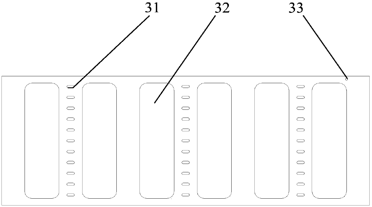
[0031] figure 2 It is a top view of a cable tray provided by an embodiment of the present invention, combined with figure 2 In this embodiment, the cable tray further includes an air cushion 3, which is fixedly installed on a plurality of crosspieces 2, and the air cushion 3 extends along the l...


PUM


Abstract

The invention discloses a cable bridge, and belongs to the field of cable installation. The cable bridge comprises two ladder edges and a plurality of crosspieces. The two ladder edges are arranged inparallel. One end of each crosspiece is fixedly mounted on one ladder edge, and the other end of each crosspiece is fixed on the other ladder edge. The crosspieces are sequentially arranged at intervals along the length direction of the ladder edges. The cable bridge also comprises an air cushion. The air cushion is fixedly arranged on the crosspieces and extends along the length direction of theladder edges. A plurality of first fixing holes are formed in the air cushion. All the first fixing holes are used for inserting ribbons. The vibration of a cable can be absorbed, and the cable is prevented from loosening due to vibration of the cable.

Description

Technical field [0001] The invention belongs to the field of cable installation, and particularly relates to a cable tray. Background technique [0002] A cable tray is a device used to lay cables. A common cable tray usually includes two ladder sides and multiple rungs. The two ladder sides are arranged parallel to each other, and one end of each rung is fixedly installed on a ladder edge. The other end of each rung is fixed on another ladder side, and each rung is arranged at intervals along the length direction of the ladder side. [0003] When laying cables through the above-mentioned cable tray, the cables are generally directly tied to the crosspieces by cable ties, so that the cables are arranged along the length of the ladder side. [0004] In the process of implementing the present invention, the inventor found that the prior art has at least the following problems: [0005] When a large current flows in the cable, under the effect of electromagnetic induction, the cable wil...

Claims


Application Information

Patent Timeline
IPC IPC(8): H02G3/04F16F15/023
CPCF16F15/0232H02G3/0406H02G3/0456
Inventor 张文亮周驰程旎席志成李海
Owner WUHAN MARINE MACHINERY PLANT
Learn More