Quick drilling equipment for production line pipe rack and drilling method thereof

A technology for drilling equipment and production lines, which is applied in the direction of drilling/drilling equipment, boring/drilling, metal processing equipment, etc., and can solve the inflexible adjustment of the drill bit position of the drilling equipment, low drilling efficiency, and debris , Dust affects normal operation and other issues

Inactive Publication Date: 2019-04-19
张燕
View PDF0 Cites 3 Cited by
  • Summary
  • Abstract
  • Description
  • Claims
  • Application Information

AI Technical Summary

Problems solved by technology

[0003] The object of the present invention is to provide a kind of fast punching equipment and punching method for the pipe arrangement of the production line, which can solve the problem that the traditional punching equipment used for the pipe arrangement of the production line is in use due to the multiple positions on the pipe arrangement. It needs to be punched, and the existing punching equipment has the defects of low drilling efficiency and slow speed when punching holes, and the drill bit of the punching equipment has the defect of inflexible position adjustment, and the drill bit drilling is also difficult when punching holes. Debris and dust are prone to flying, which is not only not environmentally friendly, but also requires manual cleaning of debris and dust. Scattered debris and dust can also easily affect the normal operation of other components on the production line

Method used


Image

  • Quick drilling equipment for production line pipe rack and drilling method thereof
  • Quick drilling equipment for production line pipe rack and drilling method thereof
  • Quick drilling equipment for production line pipe rack and drilling method thereof

Examples


Embodiment Construction

[0034] The technical solutions of the present invention will be clearly and completely described below in conjunction with the embodiments. Apparently, the described embodiments are only some of the embodiments of the present invention, not all of them. Based on the embodiments of the present invention, all other embodiments obtained by persons of ordinary skill in the art without creative efforts fall within the protection scope of the present invention.

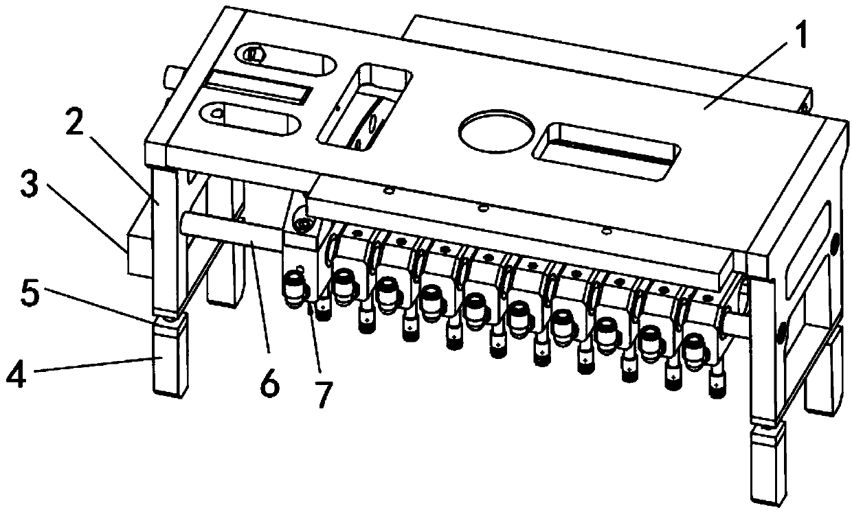
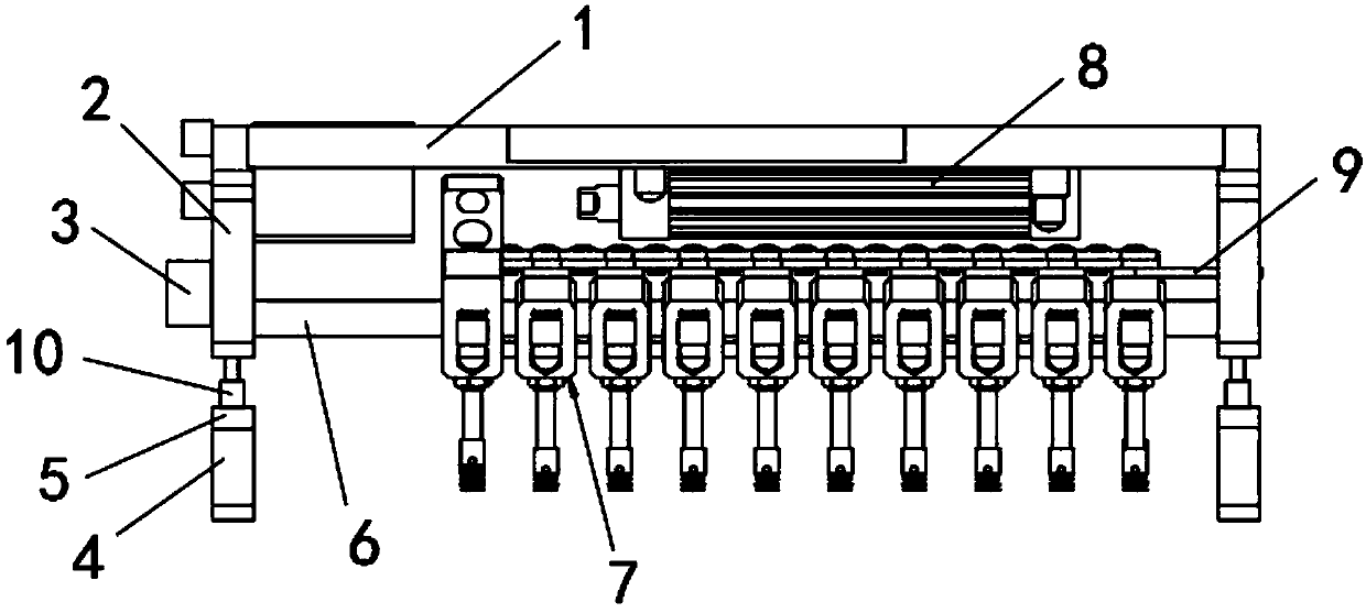
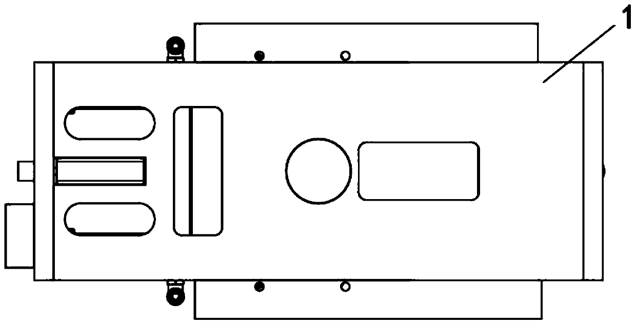
[0035] see Figure 1-10As shown, a quick punching device for pipe arrangement in a production line includes two brackets 2 and a top plate 1 fixedly installed on the top of the two brackets 2, and two piercing rods 6 are fixed by the welding machine between the two brackets 2, A punching mechanism 7 is connected between the two piercing rods 6, a PLC controller 3 is installed on the side wall of the bracket 2, two bottom supports 4 are installed on the bottom of the two brackets 2, and each bottom support 4 is installed on ...


PUM


Abstract

The invention discloses quick drilling equipment for a production line pipe rack and a drilling method thereof. The quick drilling equipment can solve the problems that as multiple locations on the pipe rack need to be drilled, traditional drilling equipment for the production line pipe rack has low drilling efficiency and low drilling speed when drilling, a drill bit of the drilling equipment isinflexible in position adjustment, and the drill bit and the holes cause debris and dust easily during drilling; the prior drilling equipment is not only no environmentally friendly, but also requiresmanual removal of the debris and dust; the scattered debris and dust are also prone to affecting the normal operation of the remaining components in the production line. The quick drilling equipmentcomprises two brackets and a roof fixedly installed on the top of the two brackets; two piercing rods are welded and fixed between the two brackets; a drilling mechanism is connected between the two piercing rods in a penetrating mode; a PLC is installed on the side wall of each bracket; and two bottom supports are installed at the bottom of the two brackets.

Description

technical field [0001] The invention relates to a punching device, in particular to a fast punching device and a punching method for pipe arrangement in a production line. Background technique [0002] The pipes on the production line need to be punched, and punching requires the use of punching equipment. However, there are still certain defects in the existing punching equipment used for pipe arrangement in the production line, because multiple positions on the pipe arrangement need to be punched, and the existing punching equipment has punching holes when punching holes. The defect of low hole efficiency and slow speed, and the position adjustment of the drill bit of the drilling equipment is not flexible. At the same time, the drill bit is also prone to debris and dust flying when drilling. Manual cleaning is required, and scattered debris and dust can easily affect the normal operation of other components on the production line. Contents of the invention [0003] Th...

Claims


Application Information

Patent Timeline
IPC IPC(8): B23B39/16B23B41/00B23B47/00B23Q11/00
CPCB23B41/00B23B39/161B23B47/00B23Q11/0046
Inventor 张燕
Owner 张燕
Why Eureka
Try Eureka