Mounting structure of integrated suspended ceiling

An installation structure and integrated ceiling technology, which is applied to ceilings, building components, lighting devices, etc., can solve the problems of complex structure, cumbersome installation process, and difficulty in ensuring stability, so as to achieve the effect of ensuring stability and preventing scattering

Pending Publication Date: 2019-04-19
嘉兴富得利厨卫科技有限公司
View PDF0 Cites 3 Cited by
  • Summary
  • Abstract
  • Description
  • Claims
  • Application Information

AI Technical Summary

Problems solved by technology

In order to pursue stability, some current suspended ceilings often have complex structures, which makes the installation process more cumbersome; while some suspended ceilings with relatively simple structures are difficult to ensure their stability after installation.

Method used


Image

  • Mounting structure of integrated suspended ceiling
  • Mounting structure of integrated suspended ceiling
  • Mounting structure of integrated suspended ceiling

Examples


Embodiment 1

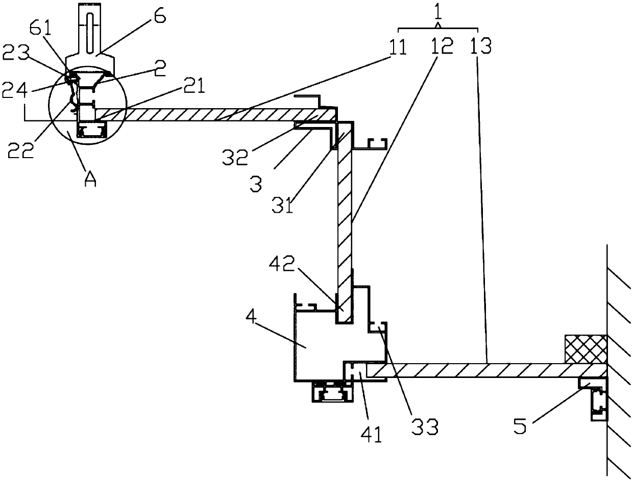
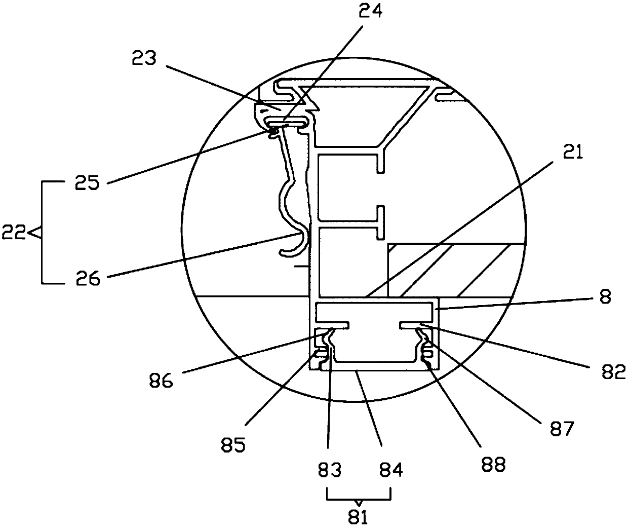
[0023] Such as figure 1 The installation structure of an integrated suspended ceiling shown includes a decorative panel 1 and a connecting assembly connected with the decorative panel 1, the decorative panel 1 is respectively connected with the wall and the ceiling through the connecting assembly, and the decorative panel 1 includes a first transverse Plate 11, vertical plate 12 and second horizontal plate 13, the connecting assembly includes connecting piece 2, secondary beam internal angle line 3, secondary beam structural member 4, top internal angle line 5, hanging piece 6, the hanging The piece 6 is mounted on the connecting piece 2, the bottom of the hanging piece 6 is a hook part 61, and the hanging part 61 has a shape with a large opening and a small bottom and matches the shape of the top of the connecting piece 2. The secondary beam The inner corner line 3 is provided with a lower card slot 31 opening downward and a left card slot 32 opening to the left. One end of t...

Embodiment 2

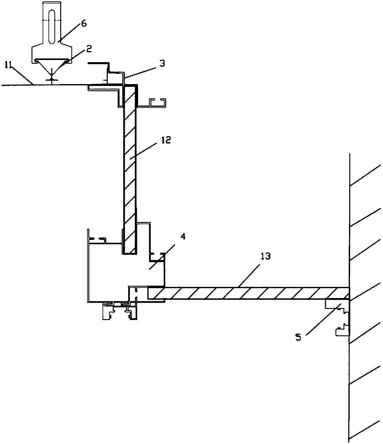
[0032] Such as image 3 As shown, the difference between this embodiment and the installation structure of the above-mentioned integrated ceiling is that the two adjacent first horizontal plates 11 in this embodiment are both gusset plates, the connecting piece 2 adopts a triangular keel, and the gusset plates are turned over and clamped. Insert it into the card slot under the triangular keel to achieve fixation, so as to realize diversified matching and conversion, and meet various humanized choices.

Embodiment 3

[0034] Such as Figure 4 As shown, the difference between this embodiment and the installation structure of the above-mentioned integrated ceiling is that the two adjacent first horizontal plates 11 in this embodiment are both wood-plastic boards, and a flat plate 28 is provided at the bottom of the connecting piece 2, and the The bottom of the flat plate 28 is attached to a first horizontal plate 11, and one end of the flat plate 28 is folded down and extended to the left side to form a card and part 27, and the insertion of the adjacent two first horizontal plates 11 forms a connection with the first horizontal plate 11. The engaging groove 14 where the card fits with the portion 27 .

[0035]In this embodiment, a decorative lamp 9 is fixed under the first horizontal plate 11. The decorative lamp 9 includes a second U-shaped groove 91 and a second light-transmitting plate 92. The second light-transmitting plate 92 includes a first Two locking arms 93 and a second cover plat...


PUM


Abstract

The invention discloses a mounting structure of an integrated suspended ceiling. The mounting structure comprises a decorative panel and a connecting assembly connected with the decorative panel, wherein the decorative panel is separately connected with a wall body and a ceiling by virtue of the connecting assembly. The mounting structure is characterized in that the decorative panel comprises a first transverse plate and a second transverse plate, the connecting assembly comprises a connecting piece, a two-level beam structural piece, a top internal corner line and a suspension sheet, the suspension sheet is carried on the connecting piece, the bottom of the suspension sheet is a suspension clasp part, the suspension clasp part is matched with the top shape of the connecting piece, one end of the second transverse plate is connected with the two-level beam structural piece, the other end is fixedly in lap joint with the top of the top internal corner line, and the top internal cornerline is connected with the wall body.

Description

technical field [0001] The invention relates to an installation structure of an integrated suspended ceiling. Background technique [0002] The integrated ceiling occupies a very important position in the entire interior decoration. Appropriate decoration on the top surface of the interior can not only beautify the interior environment, but also create a colorful artistic image of the interior space. When choosing the fixing material of the suspended ceiling, the principles of material saving, firmness, safety, beauty and use should be followed. In order to pursue stability, some current suspended ceilings often have complex structures, which makes the installation process more cumbersome; while some suspended ceilings with relatively simple structures are difficult to ensure their stability after installation. Contents of the invention [0003] The object of the present invention is to overcome the above-mentioned shortcomings in the prior art, and provide an installatio...

Claims


Application Information

Patent Timeline
Patent Type & Authority Applications(China)
IPC IPC(8): E04B9/00E04B9/06E04B9/24E04B9/28E04B9/30F21V33/00
CPCE04B9/00E04B9/06E04B9/064E04B9/241E04B9/28E04B9/30F21V33/00
Inventor 何雪光张坤
Owner 嘉兴富得利厨卫科技有限公司
Why Eureka
Try Eureka