Vacuum conducting ring abrasive dust imaging monitoring device

A technology for monitoring devices and conductive rings, which can be used in measuring devices, televisions, electrical components, etc., and can solve problems such as electrification of conductive ring wear debris

Inactive Publication Date: 2019-04-26
HARBIN INST OF TECH
View PDF5 Cites 0 Cited by
  • Summary
  • Abstract
  • Description
  • Claims
  • Application Information

AI Technical Summary

Problems solved by technology

Due to factors such as the electric field generated by the power transmission of the conductive ring and the friction between the brush and the ring plate, it may lead to electrification of the conductive ring wear debris

Method used


Image

  • Vacuum conducting ring abrasive dust imaging monitoring device
  • Vacuum conducting ring abrasive dust imaging monitoring device
  • Vacuum conducting ring abrasive dust imaging monitoring device

Examples


Embodiment 1

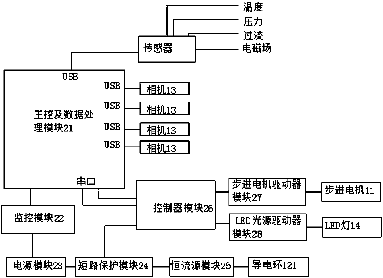
[0054] Table 1 Communication protocol between the main control module and the controller

[0055]

[0056]

[0057]

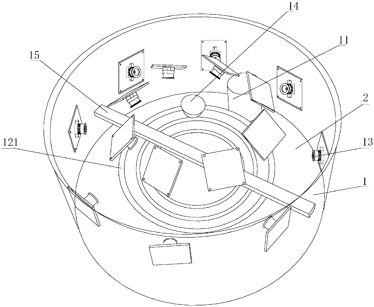
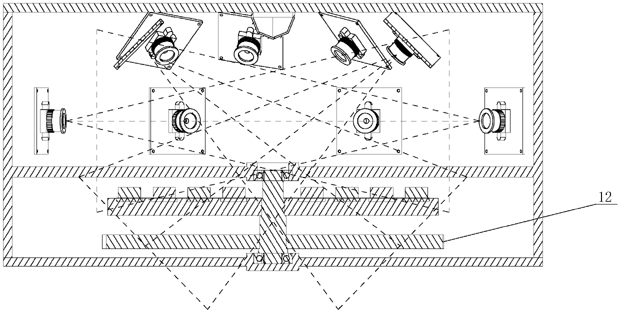
[0058] To sum up, this vacuum conductive ring wear debris imaging monitoring device, after the test starts, first extracts the image brightness at the position of the brightness standard block, and then corrects the image brightness. At this time, there is no wear debris inside the vacuum chamber 1, and the two The first image is used as a reference image. After the stepping motor 11 starts to rotate, the camera 13 is controlled for imaging. The image obtained by each imaging is corrected according to the brightness of the standard block, and the difference image is used to detect the position of the wear debris in the image. 13 After installation, calibrate the camera 13 to obtain the spatial pose relationship and the overlapping area of ​​the field of view of the two cameras 13, eliminate repeated wear debris in the image based on this information, an...


PUM


Abstract

The invention discloses a vacuum conducting ring abrasive dust imaging monitoring device which comprises a vacuum cavity and a base. The vacuum cavity is fixed to the base, a stepping motor with a gear and a transmission gear are installed on the base inside the vacuum cavity, cameras are annularly distributed on the top and the inner side face of the vacuum cavity, and an LED lamp is installed inthe center of an upper cover of the vacuum cavity; the gear of the stepping motor is meshed with the transmission gear to drive the transmission gear to rotate, a conducting ring is installed on thetransmission gear, after an experiment is started, firstly, the image brightness at the position of a brightness standard block is extracted, then, the image brightness is corrected, at the moment, noabrasive dust is generated inside the vacuum cavity, two images are adopted as reference images for use, after the stepping motor starts to rotate, the cameras perform imaging, the obtained images obtained after each imaging are corrected according to the brightness of the standard block, the differential images are used for detecting the position of the abrasive dust in the images, the space pose relation and the view field overlapping region of the two cameras are obtained, and the abrasive dust is projected on the surface of the conducting ring to obtain abrasive dust distribution.

Description

technical field [0001] The invention relates to a wear dust imaging device, in particular to a vacuum conductive ring wear dust imaging monitoring device. Background technique [0002] Conductive rings are widely used in industrial sectors, and most of them operate under various harsh conditions. Due to factors such as the electric field generated by the power transmission of the conductive ring and the friction between the brush and the ring plate, the wear debris of the conductive ring may be electrified. Therefore, monitoring the wear debris of the conductive ring is of great significance for in-depth identification of product characteristics and ensuring the safe and reliable operation of the conductive ring. [0003] Studies have shown that the wear debris generated by the relative sliding of the slip ring brush and the conductive ring has complex causes and many influencing factors. Changes in material composition, contact pressure, roughness, rotational speed, curren...

Claims


Application Information

Patent Timeline
Patent Type & Authority Applications(China)
IPC IPC(8): G01N3/56G01N3/06G06T7/80H04N7/18
CPCG01N3/068G01N3/56G01N2203/0005G01N2203/0274G01N2203/0647G06T7/80H04N7/181
Inventor 刘鹏金野吴锐赵巍刘家锋唐降龙
Owner HARBIN INST OF TECH
Why Eureka
Try Eureka