Method and arrangement for a rapid and robust chromatic confocal 3D measurement technique

a chromatic confocal and 3d measurement technology, applied in the field of three-dimensional measurement, can solve the problems of limited depth measurement and depth resolution, poor economic use of the area sensor, and reputation of being complicated for evaluation

Active Publication Date: 2010-08-31
SIRONA DENTAL SYSTEMS
View PDF7 Cites 171 Cited by
  • Summary
  • Abstract
  • Description
  • Claims
  • Application Information

AI Technical Summary

Benefits of technology

[0011]The objective of the present invention is to provide a universally applicable optical measuring method and measuring system with calibration for fast, three-dimensional measurement in commercial applications.
[0012]The technical objective of the present invention is to increase the robustness of fast three-dimensional optical measurement of the shape of objects or the shape and position of one or more objects of all kinds, including measurement on-a microscopic scale. Therefore, the objective is to generate geometrical information and not the generation of spectroscopic information.SUMMARY OF THE INVENTION
[0013]It is an object of the present invention to measure, using chromatic confocal techniques simultaneously in various depths of the object space using spectral referencing to improve precision by calibration during planar optical scanning of one or more objects for fast three-dimensional measurement of the shape of the object or the shape and position of one or more objects, particularly to obtain within the time frame of creating a single image, i.e. the integration time of a camera frame. The objects being scanned may be of all kinds, in technical and non-technical fields. It is desired to obtain a significantly higher spectral resolution compared with that achievable with three or four color channels using multiple color filters or an RGB color camera or a four-channel color camera.

Problems solved by technology

Thus, the achievable depth measurement and depth resolution are limited.
Because of the shift of adjacent spectra, this technique has the reputation of being complicated for evaluation and the area of the area sensor is not used economically as there is no high area filling factor.

Method used


Image

  • Method and arrangement for a rapid and robust chromatic confocal 3D measurement technique
  • Method and arrangement for a rapid and robust chromatic confocal 3D measurement technique
  • Method and arrangement for a rapid and robust chromatic confocal 3D measurement technique

Examples


Embodiment Construction

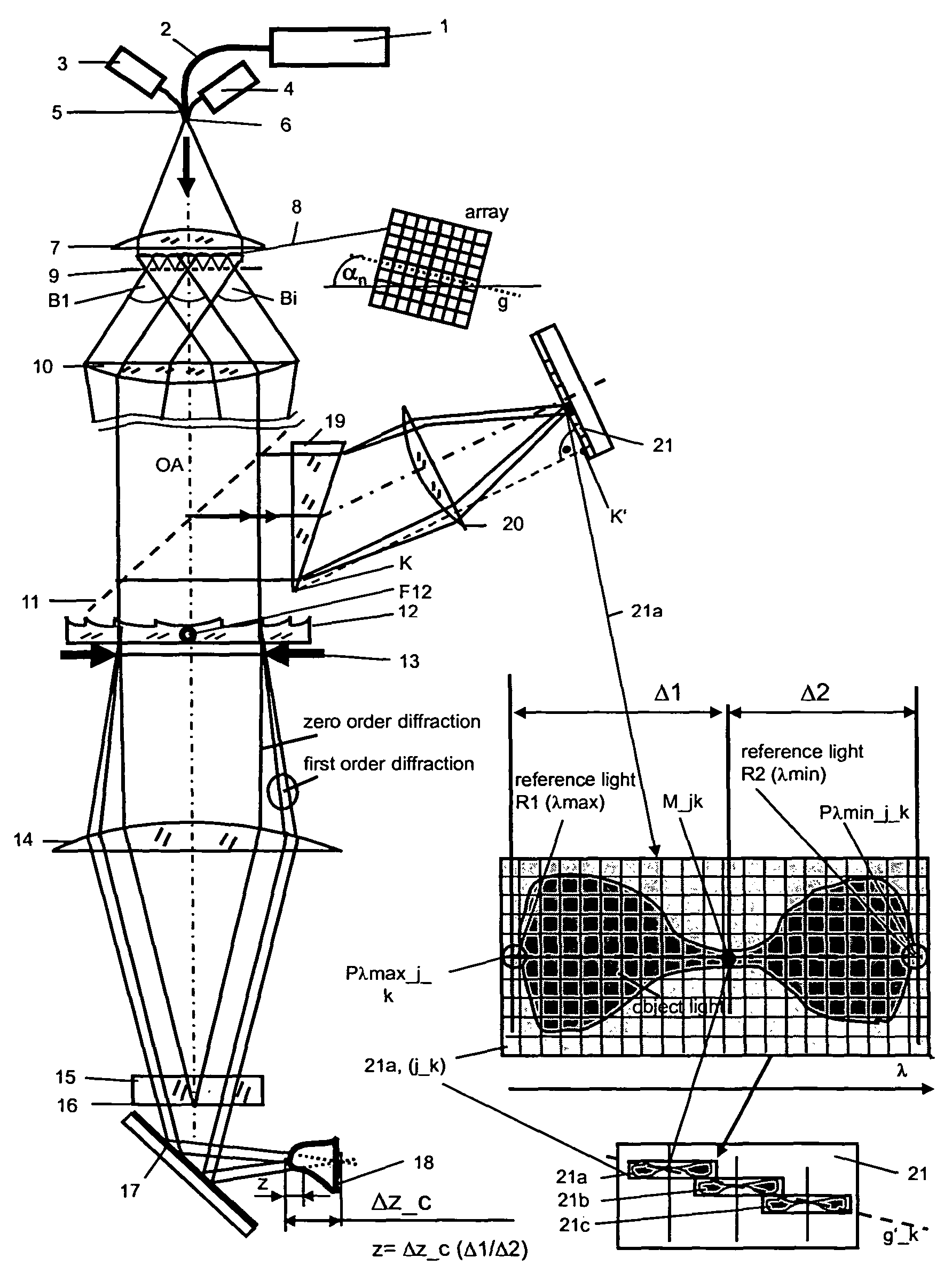
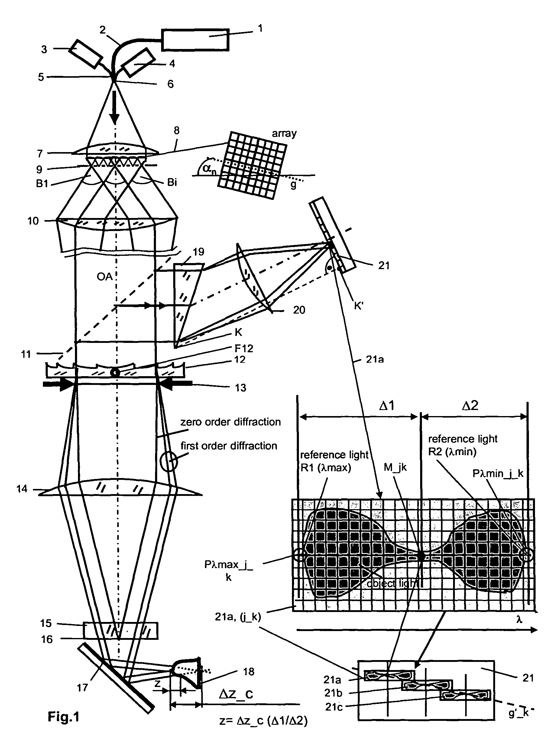
[0064]FIG. 1 represents the use of an intraoral camera for optical, three-dimensional measurement of the shape of a tooth. The polychromatic light source used for object measurement is a fiber-coupled superluminescent diode 1 having a half-width value in the order of magnitude of approximately 100 nm. The light emitted therefrom is coupled into a fiber 2.

[0065]Furthermore, a first switchable laser diode 3 and a second switchable laser diode 4 are provided, whose light is used as reference light for calibrating the system and is coupled into the fiber 2 via a Y-junction 5, or Y-junction 6, respectively. The measuring light and reference light emerging from the end of the fiber 2 passes to a collimator lens 7 for the purpose of bundle collimation. This forms at least one approximately plane wave, which passes to a microlens array 8 comprising approximately 100×150 microlenses, which form foci which impinge on an adapted and oriented pinhole array 9. The microlens array 8 and the pinho...


PUM


Abstract

A chromatic confocal technique and apparatus for the rapid three-dimensional measurement of an object shape, particularly of a tooth in a patient's jaw, using an array of polychromatic point light sources, a planar detector matrix, a beam splitter for lateral spectral separation, and an objective for illuminating and recording the object. Spectral defined reference light bundles are generated, injected into the detection beam path via a reference beam path and, following spectral splitting, are focused on the detector matrix as reference image points, wherein laterally shifted sub-matrices are numerically defined on the detector matrix for spectral analysis of the object light, which sub-matrices are implemented as spectral cells for three-dimensional measurement of the shape of the object.

Description

BACKGROUND OF THE INVENTION[0001]Confocal microscopy was proposed by Marvin Minski (cf. U.S. Pat. No. 3,013,467, Dec. 19, 1961).[0002]The chromatic confocal technique provides the possibility of effecting focusing without the need for mechanically moving parts, which as a result usually reduces measuring time significantly, as was proposed by G. Molesini in 1983 in connection with a spectrometer (cf. GB 2144537 and DE 3428593 C2). An example of successful application of the chromatic confocal approach is described in a paper by H. J. Tiziani and H.-M. Uhde “Three-dimensional image sensing by chromatic confocal microscopy” in Applied Optics, Vol. 33, No. 1, April 1994, pages 1838 to 1843. In this case the spectral analysis is performed using three color filters. Thus, the achievable depth measurement and depth resolution are limited.[0003]DE 103 21 885 A1 describes a chromatic confocal system including a component having variable refractive power, for example, a diffractive component...

Claims


Application Information

Patent Timeline
Patent Type & Authority Patents(United States)
IPC IPC(8): G01B11/24
CPCG01B11/25G06T7/0057G01B2210/50G06T7/521
Inventor KORNER, KLAUSKOHLER, CHRISTIANPAPASTATHOPOULUS, EVANGELOSOSTEN, WOLFGANG
Owner SIRONA DENTAL SYSTEMS
Why Eureka
Try Eureka