
Scanning device, its supplementary light control system and control method

A scanning device and control system technology, which is applied in the direction of instruments, induction record carriers, electromagnetic radiation induction, etc., can solve the problems of particularly obvious impact and unreadable barcode, so as to reduce the impact and improve the success rate

Active Publication Date: 2020-09-11
WUXI IDATATECHNOLOGYCOMPANYLTD
View PDF4 Cites 0 Cited by
  • Summary
  • Abstract
  • Description
  • Claims
  • Application Information

AI Technical Summary

Problems solved by technology

However, whether it is a single point light source or multiple point light sources, there will be a certain amount of reflected light that will affect the reading of barcodes, especially when reading barcodes on smooth surfaces such as metal surfaces or glass surfaces. When, the influence of reflected light is particularly obvious, resulting in unreadable barcodes

Method used


Image

  • Scanning device, its supplementary light control system and control method
  • Scanning device, its supplementary light control system and control method
  • Scanning device, its supplementary light control system and control method

Examples


Embodiment Construction

[0061] In order to facilitate a better understanding of the purpose, structure, features, and effects of the present invention, the present invention will now be further described in conjunction with the accompanying drawings and specific embodiments.

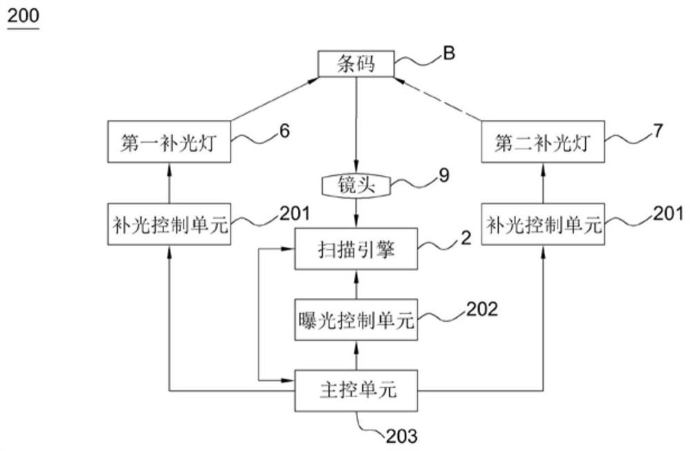
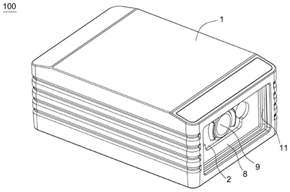
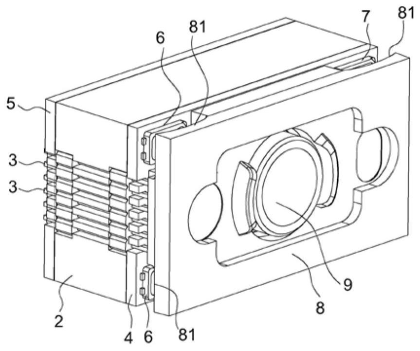
[0062] figure 1 It is a block diagram of the supplementary light control system 200 of the scanning device of the present invention. figure 2 It is a perspective view of the scanning device of the present invention. image 3 for figure 2 A perspective view of the scan engine in . Figure 4 for image 3 The decomposition diagram.

[0063] Such as Figure 1-4 As shown, the scanning device 100 has an approximately square housing 1, the front end of the housing 1 has a scanning window 11 approximately rectangular, the length direction of the scanning window 11 is arranged along the horizontal direction, the scanning device 100 also has an approximate rectangular parallelepiped scanning engine 2 accommodated in the housing 1...


PUM


Abstract

The present invention provides a scanning device, its supplementary light control system and method. The scanning device comprises: a scanning engine for collecting images and at least two supplementary lights for illuminating when the scanning engine is collecting images. The supplementary light control system includes: a supplementary light control unit, used to control at least two of the supplementary lights to emit light; an exposure control unit, used to control the exposure time of the scanning engine; a main control unit, the main control unit The unit is connected with the supplementary light control unit, and is used to control at least two supplementary light lamps to emit light alternately through the supplementary light control unit and to control the exposure time of the scanning engine to be shorter than the supplementary light through the exposure control unit. The light emitting time of a single light. It irradiates the barcode from multiple different angles through multiple indicator lights that glow alternately, reducing the influence of reflected light and improving the success rate of decoding.

Description

technical field [0001] The invention relates to a system and method for controlling a supplementary light of a scanning device, in particular to a system and a method for controlling a supplementary light for improving the decoding efficiency of a scanning device. Background technique [0002] In the barcode scanning industry, when the intensity of natural light or indoor fluorescent light cannot meet the light intensity requirements of the imaging system of the barcode reading equipment, practitioners usually use additional light sources to supplement the barcode to be read. [0003] At first, most of the industry used a single point light source for fill light. Later, in order to achieve a better fill light effect, it was gradually changed to multiple point light sources for fill light at the same time. However, whether it is a single point light source or multiple point light sources, there will be a certain amount of reflected light that will affect the reading of barcod...

Claims


Application Information

Patent Timeline
Patent Type & Authority Patents(China)
IPC IPC(8): G06K7/10
CPCG06K7/10732G06K7/10752Y02B20/40
Inventor 王冬生魏江涛覃章辉姜涛吴兴花
Owner WUXI IDATATECHNOLOGYCOMPANYLTD
Learn More