Transmitting end driving circuit and method

A driving circuit and driving method technology, applied in the direction of TV, electrical components, color TV, etc., can solve the problems of large fluctuation of impedance matching resistance and large fluctuation of driver output current, achieve good impedance matching, facilitate on-chip integration, The effect of reducing negative effects

Active Publication Date: 2019-05-07
VERISILICON MICROELECTRONICS SHANGHAI +1
View PDF10 Cites 8 Cited by
  • Summary
  • Abstract
  • Description
  • Claims
  • Application Information

AI Technical Summary

Problems solved by technology

[0006] In view of the shortcomings of the prior art described above, the purpose of the present invention is to provide a driving circuit and method for the transmitting end, which is used to solve the problem of large fluctuations in the built-in impedance matching resistance of the HDMI2.0 driver circuit and relatively large fluctuations in the driver output current in the prior art major issues

Method used


Image

  • Transmitting end driving circuit and method
  • Transmitting end driving circuit and method
  • Transmitting end driving circuit and method

Examples


Embodiment 1

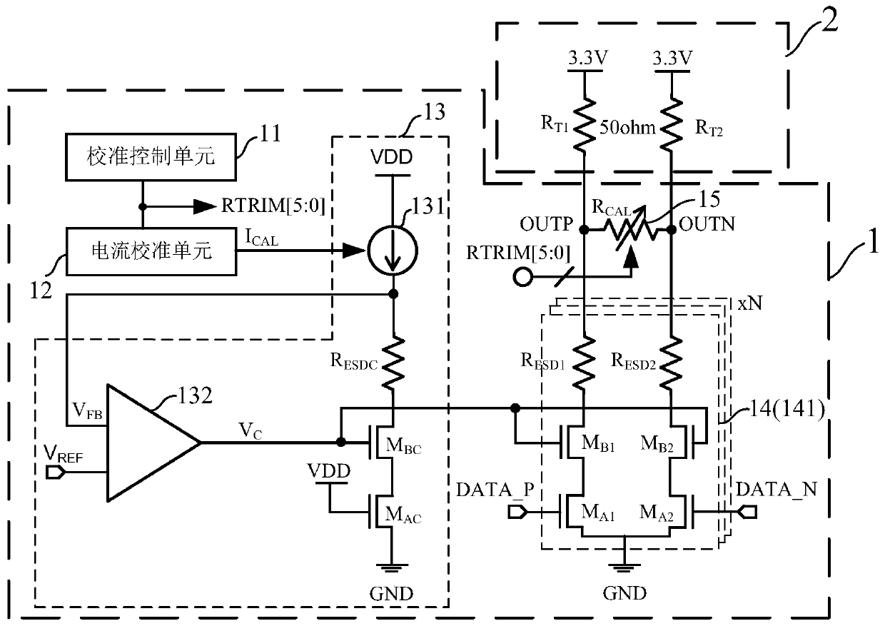
[0084] Such as figure 1 As shown, this embodiment provides a sending end driving circuit 1, and the sending end driving circuit 1 includes:

[0085] Calibration control unit 11 , current calibration unit 12 , bias voltage generation unit 13 , output stage drive unit 14 and impedance matching unit 15 .

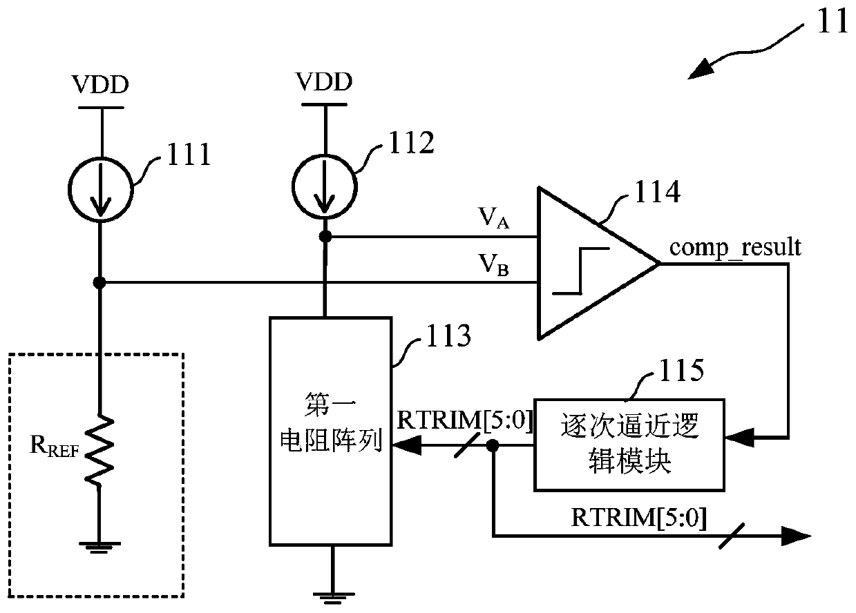
[0086] Such as figure 1 As shown, the calibration control unit 11 is used to generate a calibration control signal RTRIM[5:0] that varies with changes in process, power supply voltage and temperature.

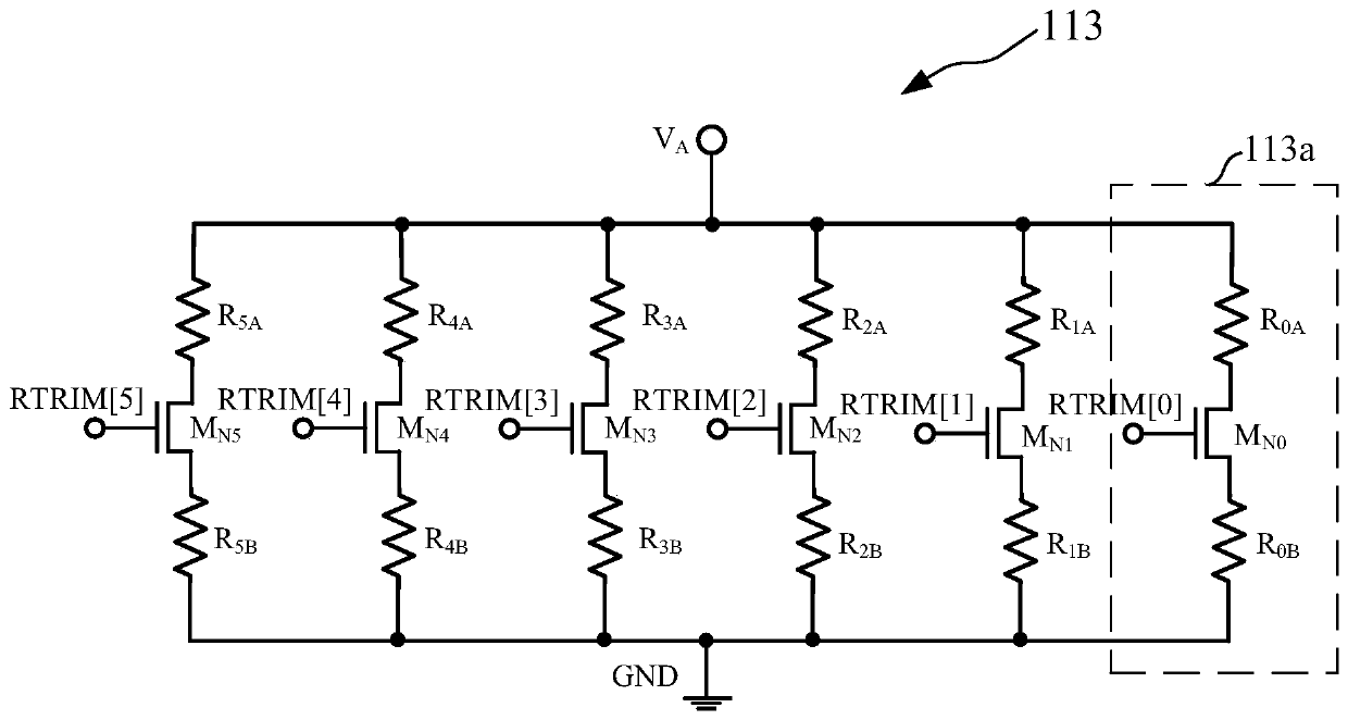
[0087] Specifically, the calibration control unit 11 gradually adjusts the resistance value of the built-in first resistor array approaching the external reference resistor gradually based on the successive approximation method, and finally the two keep the same, and sends the control signal of the first resistor array to output as the calibration control signal RTRIM[5:0]. In this embodiment, the calibration control signal is a 6-bit control bus signal, and the number of bit...


PUM


Abstract

The invention provides a transmitting end driving circuit and method. The transmitting end driving circuit comprises a calibration control unit, wherein the calibration control unit generates a calibration control signal changing along with process, power voltage or temperature; A current calibration unit that generates a calibration current based on the calibration control signal; A bias voltagegeneration unit that generates a bias voltage on the basis of the calibration current; The output stage driving unit which is used for amplifying the to-be-output signal based on the bias voltage andoutputting the amplified to-be-output signal; And an impedance matching unit that adjusts the output impedance based on the calibration control signal. the method includes: Generating a calibration control signal; Generating a calibration current based on the calibration control signal to obtain a bias voltage; Under the action of the bias voltage, amplifying a signal to be output, and obtaining astable output signal through impedance matching. According to the invention, current and resistance change caused by process, power supply voltage and temperature change is effectively reduced, the requirement of an HDMI 2.0 protocol on the amplitude change of the output voltage of the transmitting end is met, a better impedance matching effect is achieved, and the signal transmission quality iseffectively improved.

Description

technical field [0001] The invention relates to the field of integrated circuits, in particular to a sending end driving circuit and method. Background technique [0002] The driver is the key module of the sending end, which is located at the back end of the sending end. It is generally used in high-speed serial data interface circuits to send the parallel-to-serial conversion data at the sending end to the receiving end with a large driving capacity, and then can transmit data over long distances. [0003] The rapid development of the all-digital audio and video market continues to promote the high-definition multimedia interface (High Definition Multimedia Interface, HDMI) to the direction of high speed, high integration, low power consumption, and low cost. Therefore, more and more chips use low-cost and relatively Mature and reliable CMOS process design and implementation. HDMI can send audio and video signals at the same time, and is widely used in set-top boxes, DVD ...

Claims


Application Information

Patent Timeline
Patent Type & Authority Applications(China)
IPC IPC(8): H04N5/765
Inventor 李冬邢文俊汪玉馨钱哲弘
Owner VERISILICON MICROELECTRONICS SHANGHAI
Why Eureka
Try Eureka