Machine core of electric pencil-peeling device

A pencil sharpener, electric technology, applied in sharpening devices, printing, office supplies, etc., can solve the problem of inability to adjust and control the thickness of pencil sharpening

Pending Publication Date: 2019-05-10
SUNWOOD HLDG GROUP
View PDF8 Cites 4 Cited by
  • Summary
  • Abstract
  • Description
  • Claims
  • Application Information

AI Technical Summary

Problems solved by technology

[0004] The purpose of the present invention is to address the above-mentioned problems in the prior art, and propose a movement of an electric pencil sharpener, which solves the problem that the electric pencil sharpener cannot adjust and control the thickness of the pencil when it has the function of automatic shutdown. technical problem

Method used


Image

  • Machine core of electric pencil-peeling device
  • Machine core of electric pencil-peeling device
  • Machine core of electric pencil-peeling device

Examples


Embodiment 1

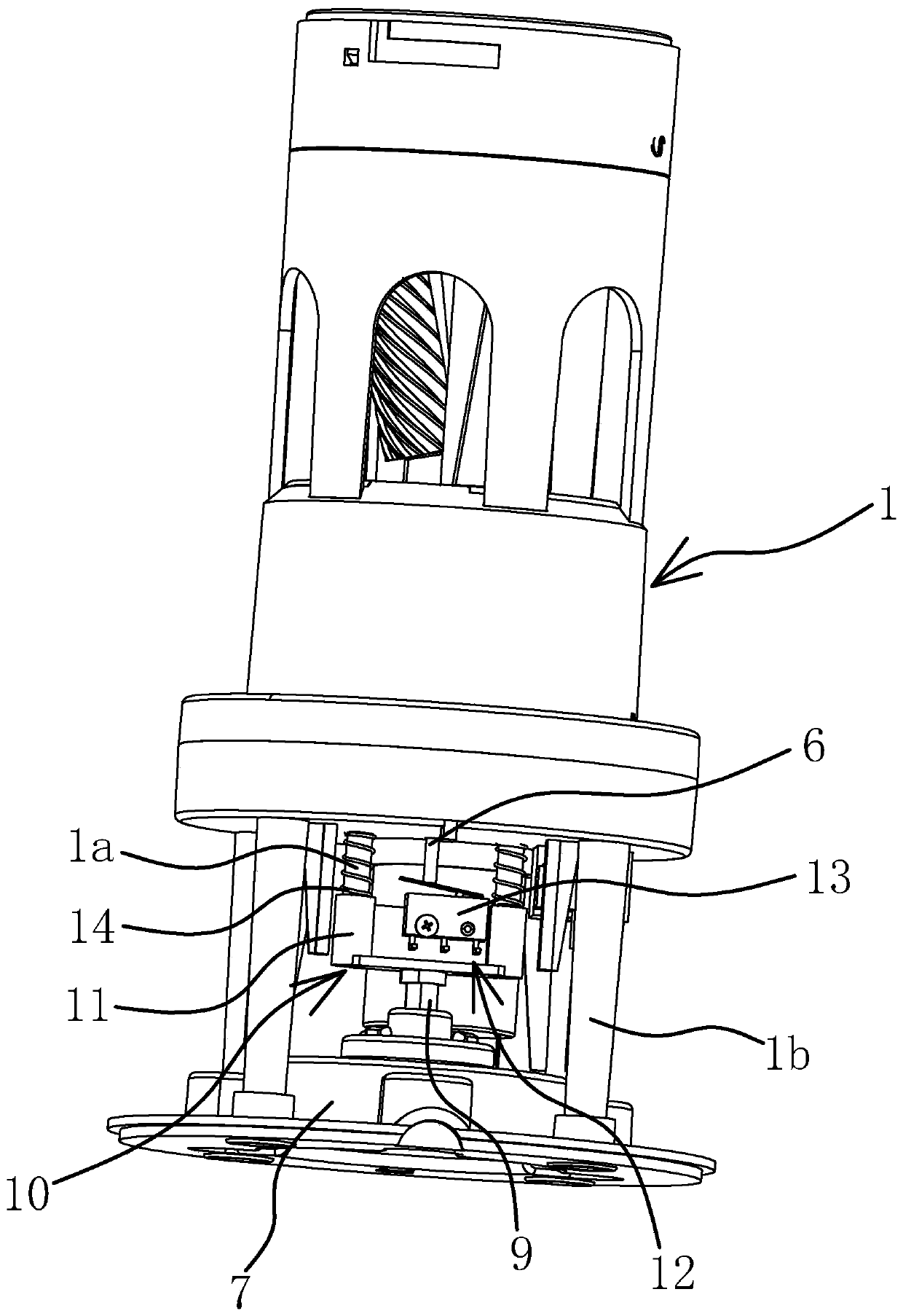
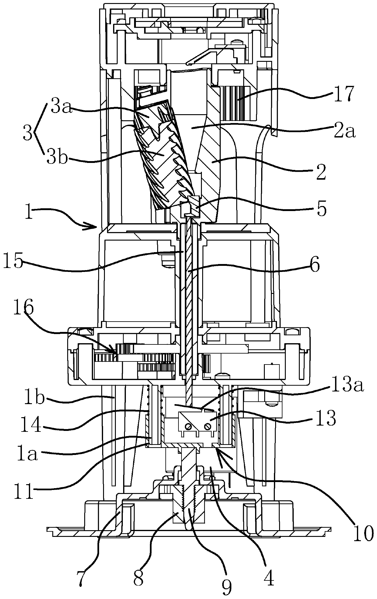
[0030] Such as figure 1 and figure 2 As shown, the movement of the electric pencil sharpener includes a bracket 1, on which a pen holder 2 with a channel 2a along the vertical direction is arranged, and a planing assembly 3 is arranged on one side of the pen holder 2, and part of the planing assembly 3 is located in the channel 2a Inside, the lower end of the support 1 is provided with a motor 4 that can control the start and stop of the planing assembly 3. Specifically, the support 1 is provided with a rotating shaft 15 along the vertical direction, and the pen holder 2 is fixed on the upper end of the rotating shaft 15. The power is transmitted between the output shafts through the gear mechanism 16. The ring gear 17 is fixed on the support 1. The planing assembly 3 includes a gear 3a that can rotate freely and a hob 3b that is coaxially arranged with the gear 3a and can rotate synchronously with the gear 3a. , The hob 3b is partly located in the channel 2a, and the gear 3...

Embodiment 2

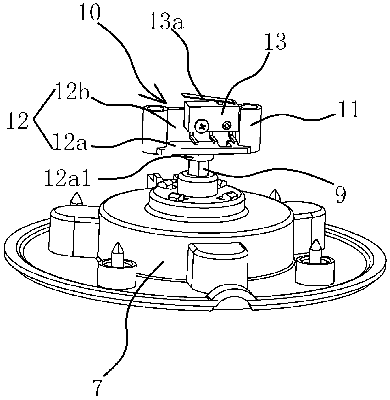
[0039] The structure and principle of this embodiment are basically the same as that of Embodiment 1, the difference is that in this embodiment, the base body 12 includes a horizontal plate 12a and a vertical plate 12b fixedly connected with the horizontal plate 12a, and the micro switch 13 is fixed On the inner side of the vertical plate 12b, the lower end of the horizontal plate 12a is fixedly connected with the upper end of the adjusting rod 9 as a whole.

Embodiment 3

[0041] The structure and principle of this embodiment are basically the same as that of Embodiment 1, the difference is that in this embodiment, the switch base 10 includes two vertical positioning columns and a seat body 12 fixed between the lower ends of the two positioning columns. , the micro switch 13 is fixed on the seat body 12 and the adjusting rod 9 is circumferentially fixed to the seat body 12, the lower end of the bracket 1 is provided with two guide heads which are hollow, and the upper ends of the two positioning posts are respectively inserted into the corresponding guide heads. Both positioning posts are equipped with spring two, the lower ends of the two springs are all against the upper end of the seat body 12, the upper ends of the two spring two are respectively against the lower end surface of the corresponding guide head, and the lower end of the seat body 12 is provided with a non-circular shape. Shaped connecting hole, the shape of the upper end of the a...


PUM


Abstract

The invention provides a machine core of an electric pencil-peeling device, belongs to the technical field of machinery, and solves the problem that the pencil planing thickness cannot be adjusted andcontrolled simultaneously when an existing electric pencil-peeling device has the automatic shutdown function. The machine core includes a bracket, a pencil holder, a planing assembly, a motor and abase connected to the lower end of the bracket, a pencil blocking block is arranged in the pencil holder, a jacking rod is arranged inside the bracket in a penetrating mode, the upper end of the jacking rod is propped against the lower end of the pencil blocking block, and an adjusting head is fixedly arranged at the lower end of the base in the axial direction; and an adjusting rod is arranged onthe base in a penetrating mode, the lower end of the adjusting rod is in threaded connection with the adjusting head, the upper end of the adjusting rod extends out of the base, a switch seat is fixedly arranged at the upper end of the adjusting rod in the circumferential direction, the switch seat is fixed to the bracket in the circumferential direction, the switch seat and the bracket are slidably connected in the vertical direction, a micro-switch is fixedly arranged on the switch seat, a trigger part is arranged on the micro-switch, the lower end of the jacking rod is propped against thetrigger part, and the micro-switch can be triggered when the jacking rod moves downwards. The machine core has the advantages that the pencil planing thickness can be adjusted and controlled while theautomatic shutdown is conducted, and the adjustment is convenient.

Description

technical field [0001] The invention belongs to the technical field of machinery and relates to an electric pencil sharpener, in particular to a movement of the electric pencil sharpener. Background technique [0002] The electric pencil sharpener is a very common office stationery in the current office or daily study life. The traditional electric pencil sharpener only has the function of dynamic planing. However, as the pace of life becomes faster and faster, people's requirements for the electric pencil sharpener Higher and higher. For this reason, the applicant has proposed the movement of the electric pencil sharpener whose application number is 201610438307.9, which includes a shell with an open upper end, a pen holder arranged in the shell, a planing assembly positioned at one side of the pen holder, and the work of the planing assembly can be controlled. There is a pen-holding channel on the pen holder, and the pen holder is provided with a pen-blocking block that c...

Claims


Application Information

Patent Timeline
Patent Type & Authority Applications(China)
IPC IPC(8): B43L23/08B43L23/02
Inventor 林夏森
Owner SUNWOOD HLDG GROUP
Why Eureka
Try Eureka