
A three-phase independent time relay

A time relay, independent technology, applied in the direction of relay base/casing/cover, etc., can solve the problems of no good elimination effect, restraint, not enough convenience, etc.

Active Publication Date: 2020-07-07
珠海天沃电力科技有限公司
View PDF5 Cites 0 Cited by
  • Summary
  • Abstract
  • Description
  • Claims
  • Application Information

AI Technical Summary

Problems solved by technology

[0002] The current relays are generally directly fixed on the corresponding position, and the target position needs to be drilled. When the relay is repaired or replaced, the original hole will be left, and there is no good elimination effect. After completion, the installation is not convenient enough and holes need to be drilled, which increases the damage to the target installation equipment or the wall. In order to solve the above-mentioned restraint problem, the present invention proposes a three-phase independent time relay

Method used


Image

  • A three-phase independent time relay
  • A three-phase independent time relay

Examples


Embodiment 1

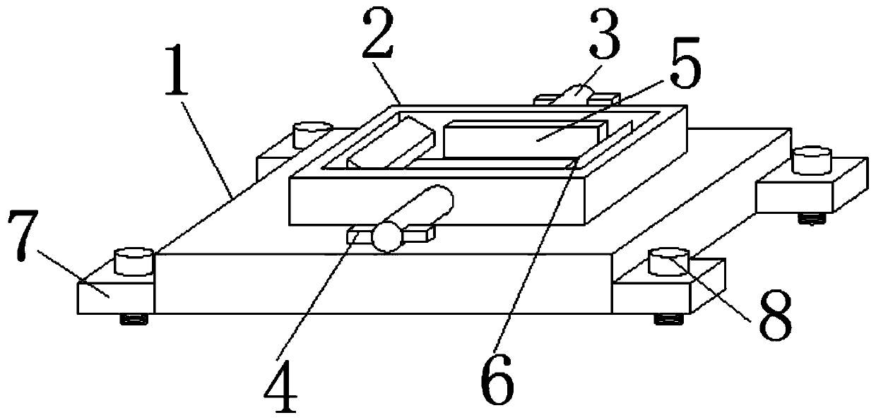
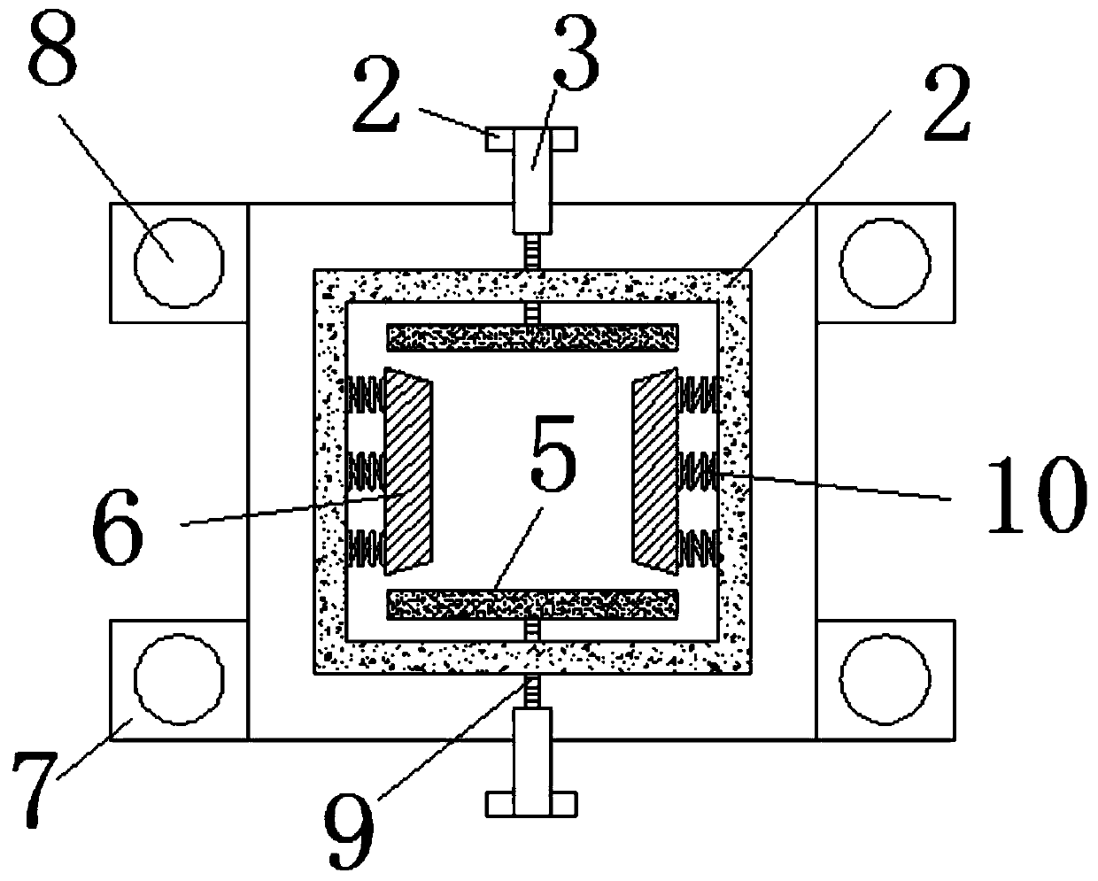
[0017] Such as Figure 1-2 As shown, a three-phase independent time relay includes a fixed base 1, a connection groove 2 is connected in the middle of one side of the fixed base 1, and a linkage shaft 3 is connected to the middle of the side plates on both sides of the connection groove 2 away from each other, and the linkage shaft 3 One end of the side plate away from the connection groove 2 and the two sides far away from each other are connected with the control board 4, the opposite sides of the connection groove 2 are provided with splints 5, and the inner side of the other pair of side plates in the connection groove 2 is provided with a fixing plate 6. The four corners of the fixed base 1 that are far away from each other are fixedly connected with connecting plates 7, and the connecting plates 7 are connected with fixing screws 8. The side of the splint 5 close to the side plate of the connecting groove 2 is connected to the threaded column 9 in the middle, and the thre...


PUM


Abstract

The invention discloses a three-phase independent time relay. The time relay comprises a fixed base; a connecting groove is connected in the middle of one side of the fixed base; a linkage shaft is respectively connected to the middle of side plates at two sides away from the connecting groove; control plates are respectively connected to one end, away from the side plates of the connecting groove, of the linkage groove and on two sides of the connecting groove away from each other; clamp plates are disposed on two opposite sides of the connecting groove; fixed plate are disposed on inner sides of the other pair of side plates in the connecting groove; joint plates are fixedly connected to four corners, away from each other, of the fixed base; set screws are connected to the joint plates;and a threaded column is connected to the middle of one sides, close to the side plates of the connecting groove, of the clamp plates. The three-phase independent time relay has the beneficial effectsthat by disposing the clamp plates, the threaded column, the linkage shafts and the control plates, the relay can be fixedly connected through the abovementioned components when being connected intothe connecting grooves; by disposing the fixed plate and a fixed spring, the relay can be reinforced on the basis of the clamp plates; and through double fixing, the relay can be effectively and fixedly connected into the connecting groove.

Description

technical field [0001] The invention relates to a relay, in particular to a three-phase independent time relay, which belongs to the technical field of relay installation and fixing. Background technique [0002] The current relays are generally directly fixed on the corresponding position, and the target position needs to be drilled. When the relay is repaired or replaced, the original hole will be left, and there is no good elimination effect. After completion, the installation is not convenient enough and holes need to be drilled, which increases the damage to the target installation equipment or the wall. In order to solve the above-mentioned restraint problem, the present invention proposes a three-phase independent time relay . Contents of the invention [0003] The technical problem to be solved by the present invention is to overcome the defects of the prior art and provide a three-phase independent time relay. [0004] In order to solve the problems of the techn...

Claims


Application Information

Patent Timeline
Patent Type & Authority Patents(China)
IPC IPC(8): H01H45/04
Inventor 周燕向琛
Owner 珠海天沃电力科技有限公司
Learn More