Cable connector assembly

a technology of connectors and connectors, applied in the direction of securing/insulating coupling contact members, coupling device connections, electrical apparatus, etc., can solve the problem of further affecting the electrical connection between the cable and the printed circuit board, and achieve the effect of better electromagnetic shielding effectiveness

Inactive Publication Date: 2013-01-08
CHENG UEI PRECISION IND CO LTD
View PDF8 Cites 46 Cited by
  • Summary
  • Abstract
  • Description
  • Claims
  • Application Information

AI Technical Summary

Benefits of technology

[0006]As described above, the contact strips of the plug shielding shell contact with the elastic strips of the receptacle shielding shell to make the plug shielding shell effectively connect with the receptacle shielding shell. Thus, a better electromagnetic shielding effectiveness is acquired to achieve a steady signal transmission between the cable and the printed circuit board.

Problems solved by technology

However, an electromagnetic interference is often apt to happen in the cable connector assembly on account of the cable connector assembly having no electromagnetic shielding function that further affects the electrical connection between the cable and the printed circuit board.

Method used


Image

  • Cable connector assembly
  • Cable connector assembly
  • Cable connector assembly

Examples


Embodiment Construction

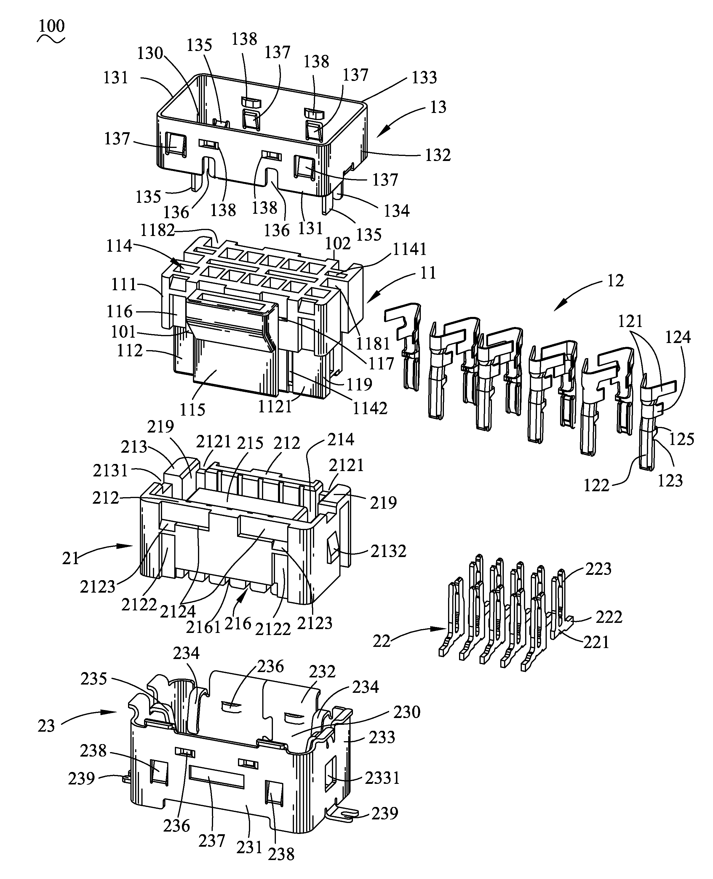
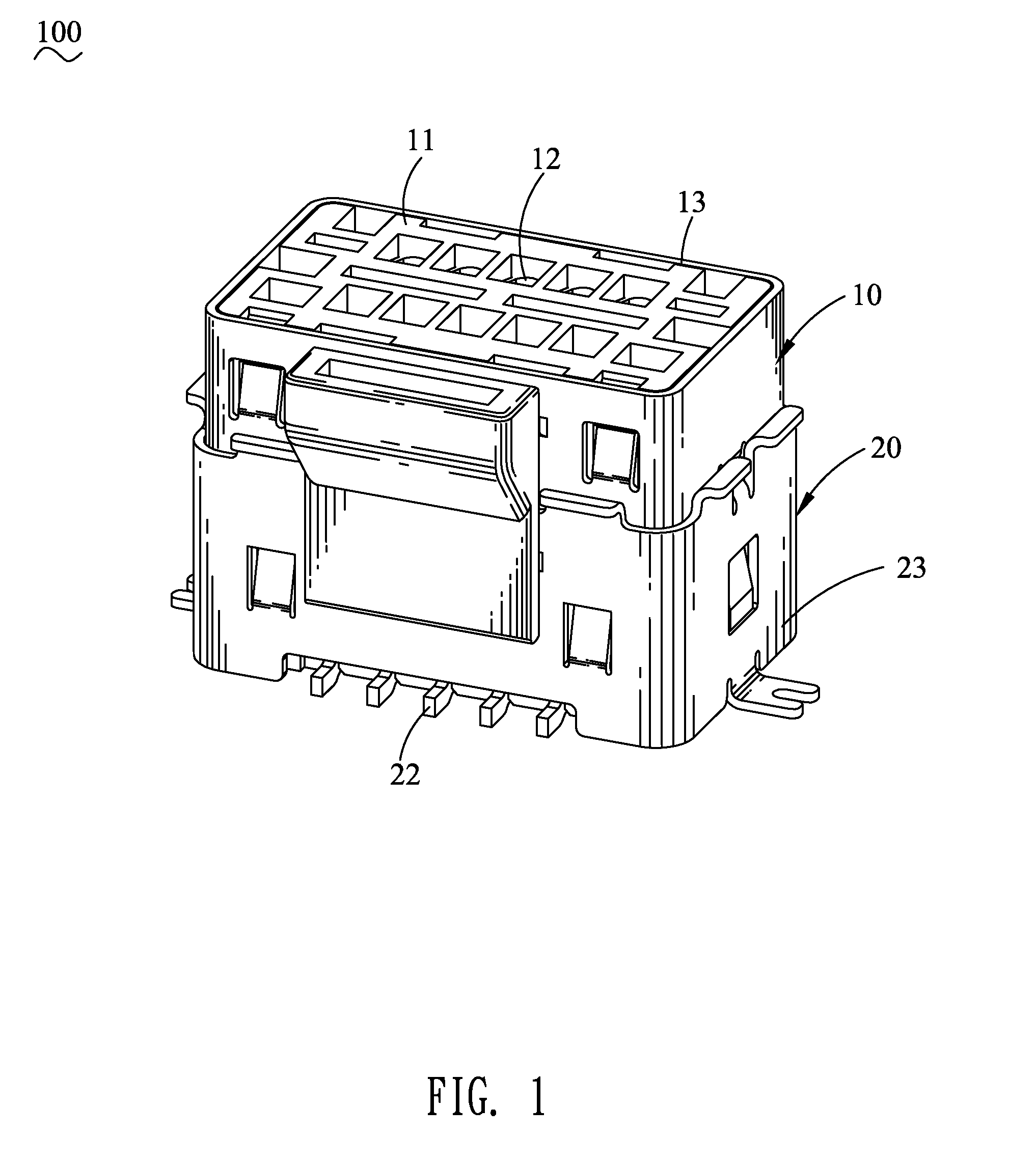
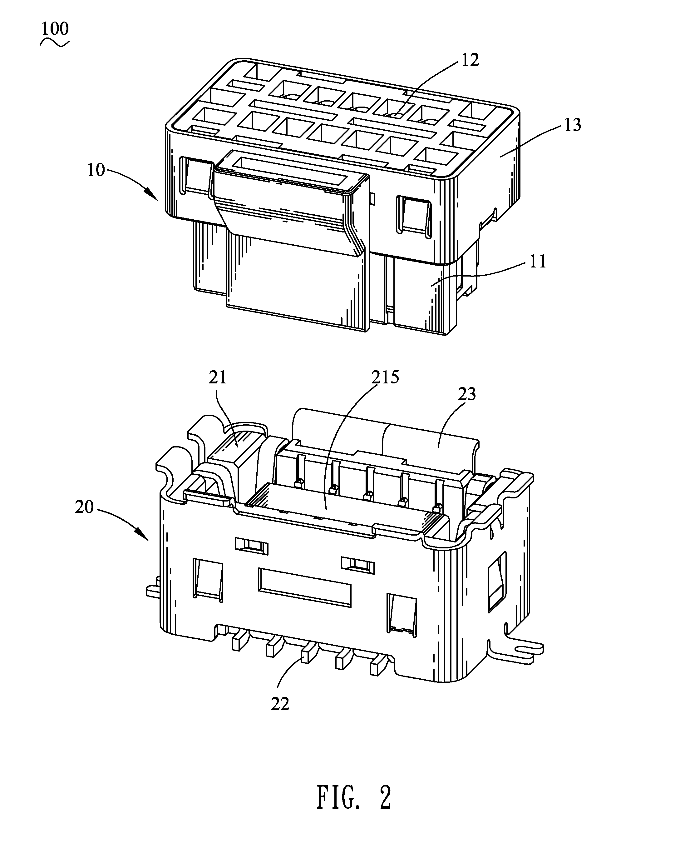
[0013]With reference to FIG. 1, FIG. 2 and FIG. 3, a cable connector assembly 100 in accordance with the present invention is shown. The cable connector assembly 100 adapted for connecting between a cable (not shown) and a printed circuit board (not shown) includes a plug connector 10 and a receptacle connector 20.

[0014]Referring to FIG. 1, FIG. 2, FIG. 3 and FIG. 5, the plug connector 10 includes a plug housing 11, a plurality of plug terminals 12 and a plug shielding shell 13. The plug housing 11 has a base portion 111 and a tongue portion 112 of a substantially rectangular hollow shape protruded downward from a middle of a bottom face of the base portion 111. Accordingly, an inserting groove 113 is formed in a middle of the tongue portion 112 and has a bottom opened freely. Two opposite ends of a front wall 1121 of the tongue portion 112 extend oppositely to form two extending walls 119 to make the front wall 1121 of the tongue portion 112 wider than a rear wall 1122 of the tongu...


PUM


Abstract

A cable connector assembly connecting between a cable and a printed circuit board includes a plug connector and a receptacle connector. The plug connector includes a plug housing, a plurality of plug terminals received in the plug housing, and a plug shielding shell surrounding the plug housing. A plurality of contact strips extend downward from a periphery of the plug shielding shell to be attached to a periphery of the plug housing. The receptacle connector includes a receptacle housing, a plurality of receptacle terminals received in the receptacle housing, and a receptacle shielding shell surrounding the receptacle housing. A plurality of elastic strips is bent inward and then downward from a periphery of the receptacle shielding shell. The plug connector is engaged with the receptacle connector with the plug terminals contacting with the receptacle terminals and the contact strips contacting with the elastic strips.

Description

BACKGROUND OF THE INVENTION[0001]1. Field of the Invention[0002]The present invention generally relates to a cable connector assembly, and more particularly to a cable connector assembly with electromagnetic shielding function.[0003]2. The Related Art[0004]Conventionally, a cable connector assembly includes a plug connector and a receptacle connector. The plug connector includes a plug housing, and a plurality of plug terminals received in the plug housing. A top end of each of the plug terminals is connected with a cable. The receptacle connector includes a receptacle housing, and a plurality of receptacle terminals received in the receptacle housing. A bottom end of each of the receptacle terminals is soldered on a printed circuit board. Then the plug connector is engaged with the receptacle connector with the plug terminals contacting with the receptacle terminals to realize an electrical connection between the cable and the printed circuit board. However, an electromagnetic inte...

Claims


Application Information

Patent Timeline
Patent Type & Authority Patents(United States)
IPC IPC(8): H01R13/648
CPCH01R12/707H01R12/716H01R13/42H01R13/6583H01R2107/00
Inventor LAN, RONG-QINXU, LI-JUNLIN, MING-HAN
Owner CHENG UEI PRECISION IND CO LTD
Why Eureka
Try Eureka