Antenna small panel, antenna structure and mobile terminal
An antenna and antenna feed point technology, which is applied in the direction of antenna grounding switch structure connection, radiation element structure, etc., can solve the problems of poor antenna performance, achieve surface current stability, reduce matching loss, and improve head-hand performance.
- Summary
- Abstract
- Description
- Claims
- Application Information
AI Technical Summary
Problems solved by technology
Method used
Image
Examples
Embodiment 1
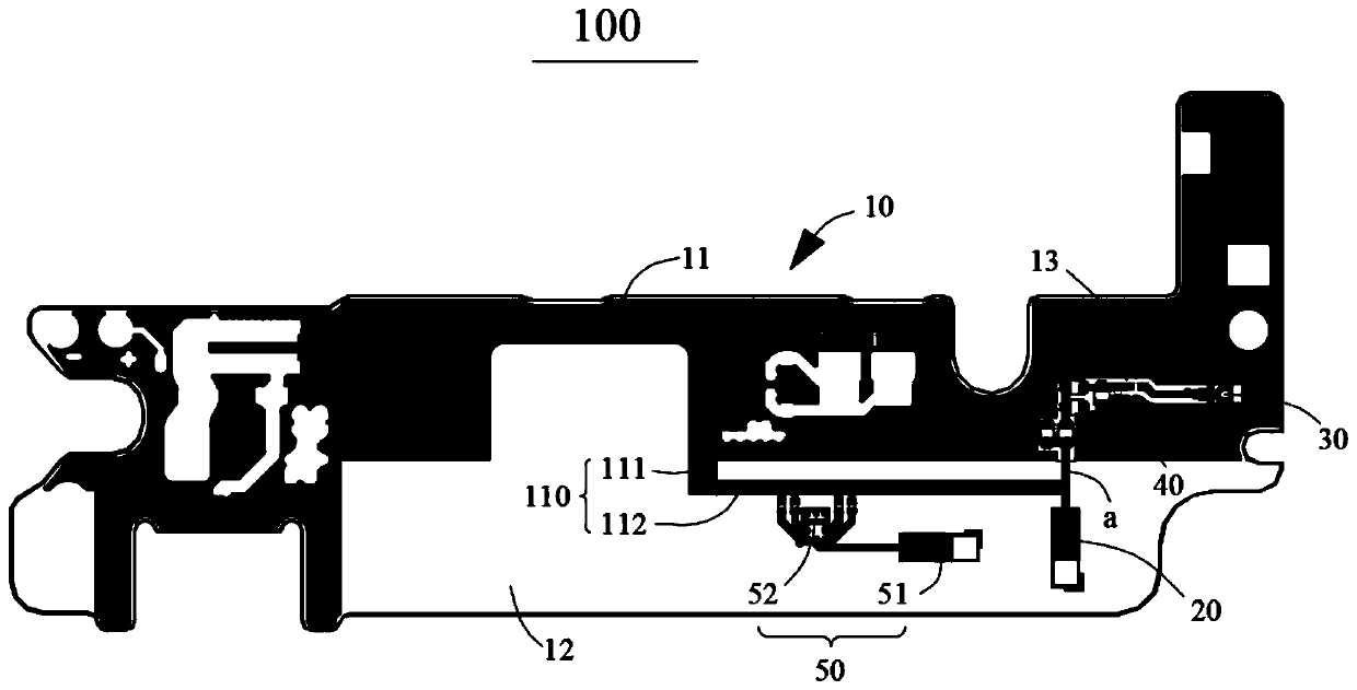
[0028] figure 1 It is a schematic top view of an antenna plate according to Embodiment 1 of the present invention.
[0029] refer to figure 1 As shown, the small antenna board 100 includes a board body 10 , an antenna feed point 20 provided on the board body 10 , a radio frequency connection 30 , an antenna matching device 40 and a tuning unit 50 . Of course, it also includes feeders connecting the various components.
[0030] One surface of the board body 10 (referring to the side surface opposite to the rear case) includes a copper laying area 11 for grounding, a wiring area 13 and a clearance area 12 for arranging components and wiring. Wherein, the copper-laying area 11, the wiring area 13 and the headroom area 12 are arranged adjacently up and down, and the copper-laying area 11 and the wiring area 13 are arranged on the same side and are all adjacent to the headroom area 12, as figure 1 As shown, the copper laying area 11 and the wiring area 13 are located on the uppe...
Embodiment 2
[0040] On the basis of the above implementation 1, this embodiment provides an antenna structure. The antenna structure of this embodiment includes the small antenna plate 100 described in Embodiment 1, the antenna and the antenna bracket, wherein the specific details of the small antenna plate 100 Refer to Embodiment 1 for the structure, and details are not repeated here.
[0041] Wherein, the antenna support is opposite to the small antenna plate, the antenna is arranged on the side of the antenna support away from the small antenna plate, the antenna support is provided with a through hole, and the antenna passes through the small antenna plate. The through hole is connected with the antenna feed point on the small antenna plate. Preferably, the antenna is a PIFA antenna.
[0042] Wherein, when the tuning unit is provided on the small antenna plate, the antenna is respectively connected to the antenna feed point and the tuning unit (that is, the tuning point of the antenna...
Embodiment 3
[0044] On the basis of the above-mentioned embodiment 2, this embodiment provides a mobile terminal including the antenna structure of Embodiment 2, wherein, for the specific structure of the antenna structure, refer to Embodiment 2, and the antenna platelet 100 involved in the antenna structure is specifically Referring to Embodiment 1, details are not repeated here.
PUM
 Abstract
Description
Claims
Application Information
 - R&D
- Intellectual Property
- Life Sciences
- Materials
- Tech Scout
- Unparalleled Data Quality
- Higher Quality Content
- 60% Fewer Hallucinations
Browse by: Latest US Patents, China's latest patents, Technical Efficacy Thesaurus, Application Domain, Technology Topic, Popular Technical Reports.
© 2025 PatSnap. All rights reserved.Legal|Privacy policy|Modern Slavery Act Transparency Statement|Sitemap|About US| Contact US: help@patsnap.com

