SMT mounting steel mesh for increasing tin soldering amount

A stencil and soldering technology, which is applied to screen printing machines, printed circuits assembled with electrical components, rotary printing machines, etc., can solve the problem that the amount of tin can not be satisfied, etc.

Pending Publication Date: 2019-05-10
苏州市吴通智能电子有限公司
View PDF0 Cites 0 Cited by
  • Summary
  • Abstract
  • Description
  • Claims
  • Application Information

AI Technical Summary

Problems solved by technology

[0003] Some current circuit boards require 100% tinning after the furnace to mount the castle-shaped pads

Method used


Image

  • SMT mounting steel mesh for increasing tin soldering amount
  • SMT mounting steel mesh for increasing tin soldering amount

Examples


Example Embodiment

[0018] Example one:

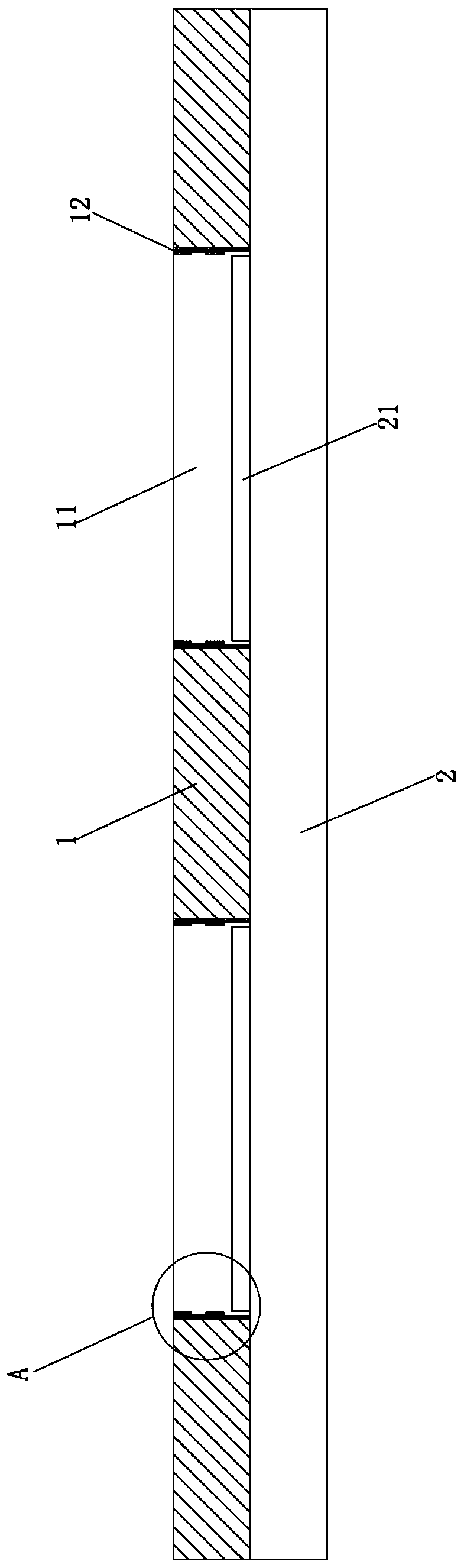
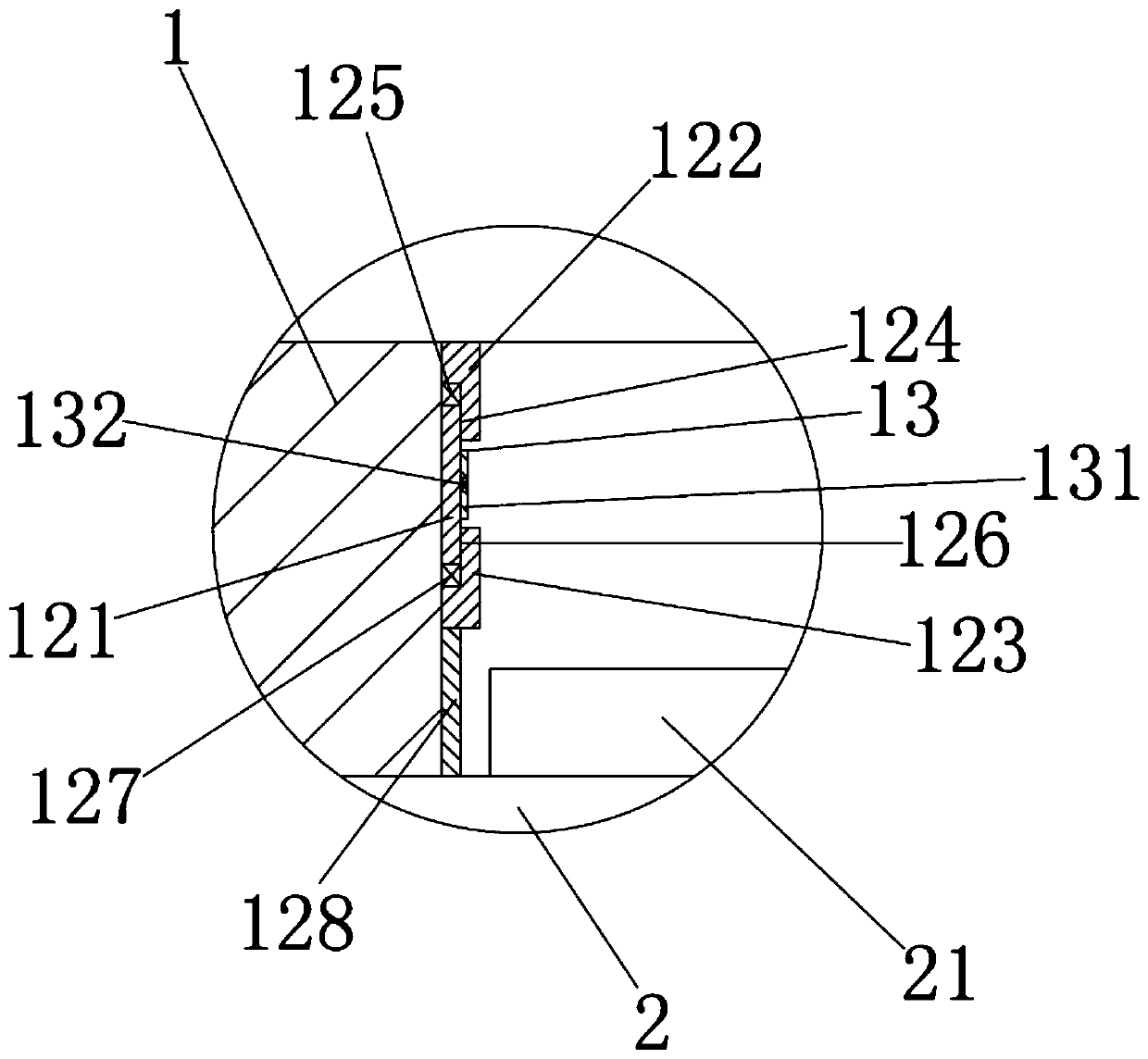
[0019] See Figure 1 to Figure 2 , The figure shows a stencil for SMT mounting with increased soldering volume provided by the first embodiment of the present invention, which includes a stencil substrate 1, on which a plurality of solder holes 11 are opened, and 11 sets of solder holes On the electronic component 21 of the circuit board 2, a plurality of solder diversion mechanisms 12 are provided on the wall of the solder hole 11, and the solder diversion mechanism 12 includes a mounting base 121 fixedly mounted on the hole wall of the solder hole 11. The opposite sides of the base block 121 are respectively elastically connected with a first diversion block 122 and a second diversion block 123, the end of the first diversion block 122 extends toward the top hole of the solder hole 11, and the second diversion block 123 The ends of the two extend in the direction of the circuit board 2.

[0020] The stencil for SMT mounting provided by this embodiment to i...

Example Embodiment

[0021] Embodiment two:

[0022] See Figure 1 to Figure 2 , The figure shows a steel mesh for SMT mounting with increased soldering volume provided by the second embodiment of the present invention. On the basis of the above-mentioned embodiment, this embodiment further makes the following as an improved technical solution: A first installation groove 124 is opened on the end surface of a flow guide block 122, the end of the installation base block 121 is inserted into the first installation groove 124, and the first spring 125 is installed in the first installation groove 124; at the same time, the second flow guide The end surface of the block 123 is provided with a second installation groove 126, the end of the installation base block 121 is inserted into the second installation groove 126, and a second spring 127 is installed in the second installation groove 126.

[0023] Through the arrangement of the above structure, the installation of the first air guide block and the sec...

Example Embodiment

[0024] Embodiment three:

[0025] See Figure 1 to Figure 2 , The figure shows a stencil for SMT mounting with increased solder volume provided in the third embodiment of the present invention. On the basis of the above-mentioned embodiment, this embodiment further makes the following as an improved technical solution: The ends of the two air guiding blocks 123 are connected with a third air guiding block 128 extending in the direction of the circuit board 2; the third air guiding block 128 is a rectangular air guiding block. Through the arrangement of the above-mentioned structure, the further diversion of the solder to the bottom of the electronic component can be realized.


PUM


Abstract

The invention provides an SMT mounting steel mesh for increasing the tin soldering amount. The SMT mounting steel mesh comprises a steel mesh substrate; multiple tin soldering holes are formed in thesteel mesh substrate; the tin soldering holes sleeve an electronic component of a circuit board; multiple tin soldering guide mechanisms are arranged on the hole walls of the tin soldering holes; thetin soldering guide mechanism comprises an installation base block fixedly installed on the hole wall of the tin soldering hole; a first guide block and a second guide block are respectively connectedat the two opposite sides of the installation base block elastically; the end part of the first guide block extends towards the top hole of the tin soldering hole; and the end part of the second guide block extends towards the direction of the circuit board. Compared with the prior art, the SMT mounting steel mesh for increasing the tin soldering amount has the advantages that: the tin solderingamount can be effectively increased; and the purpose of realizing 100% tin climbing behind the furnace is realized.

Description

technical field [0001] The invention relates to the field of SMT mounting and processing, in particular to a steel mesh for SMT mounting which improves the amount of solder. Background technique [0002] In the current SMT manufacturing process, the stencil is a fixture for printing solder paste on the circuit board before assembly in the SMT factory. The openings of the stencil mainly correspond to the solder-proof window layer of the circuit board. Only the circuit board of the stencil will open the mesh window, and the overall size of the substrate of the steel mesh corresponds to the size of the circuit board. [0003] Some current circuit boards require 100% tinning after the furnace for the placement of castle-shaped pads on the main board during soldering process, but the current amount of tinning cannot meet this requirement of tinning. Contents of the invention [0004] In view of this, the present invention provides a stencil for SMT mounting that can realize 10...

Claims


Application Information

Patent Timeline
IPC IPC(8): H05K3/34B41F15/36
Inventor 裴忠辉
Owner 苏州市吴通智能电子有限公司
Why Eureka
Try Eureka