Drillable stage hoop

A technology of grading hoops and sliding sleeves, which is applied in earthwork drilling, wellbore/well components, sealing/isolation, etc. It can solve the difficulty of inner casing going down, the inability to close the cement slurry circulation hole, and the failure to open the cement slurry circulation hole And other issues

Pending Publication Date: 2019-05-21
QINGDAO HAIFUAO IND TRADE
View PDF0 Cites 2 Cited by
  • Summary
  • Abstract
  • Description
  • Claims
  • Application Information

AI Technical Summary

Problems solved by technology

In the cementing process of existing drillable grading hoops, the following situations may occur that cause the cement slurry circulation hole to be unable to be effectively opened and closed: (1) The gravity plug and the gravity plug seat may fail to seal during the gravity plug drop process, resulting in cement failure. The opening of the slurry circulation hole fails; (2) When the opening pin breaks, the residual protrusion on the fracture surface is embedded in the inner sleeve, making it difficult for the inner sleeve to go down, which makes the opening of the slurry circulation hole fail; (3) If the operation error on the well leads to the wrong application of If the pressure is too large, the slider will press the aluminum alloy to close the plug seat with a great radial force at the moment of the slider limit, and when the radial force is greater than the mechanical properties of the aluminum alloy, it will cause the plug seat to be closed Deformation, the limit of the slider fails, and the inner sleeve continues to go down, so that the cement slurry circulation hole is closed at the moment of opening; (4) The closing pin is irregularly broken and has an uncertain fracture position when it breaks, which makes the closing pin in the After the fracture occurs, the irregular fracture surface affects or even prevents the downward movement of the closing plug seat, which makes the slider unable to retreat into the groove of the closing plug seat, and the inner sleeve cannot release the position restriction, cannot go down, and cannot realize the control of the cement slurry circulation hole. closure

Method used


Image

  • Drillable stage hoop
  • Drillable stage hoop
  • Drillable stage hoop

Examples


Embodiment Construction

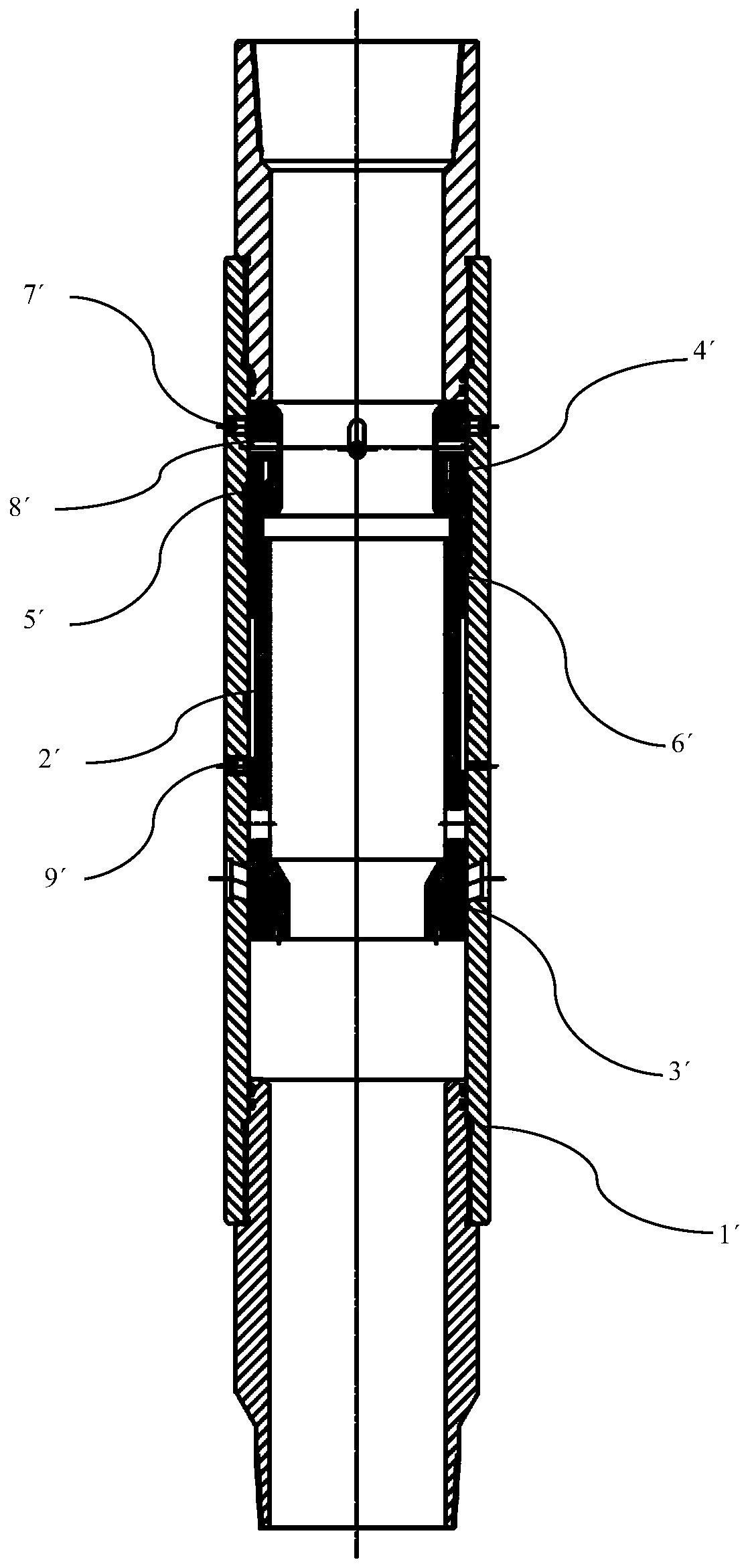
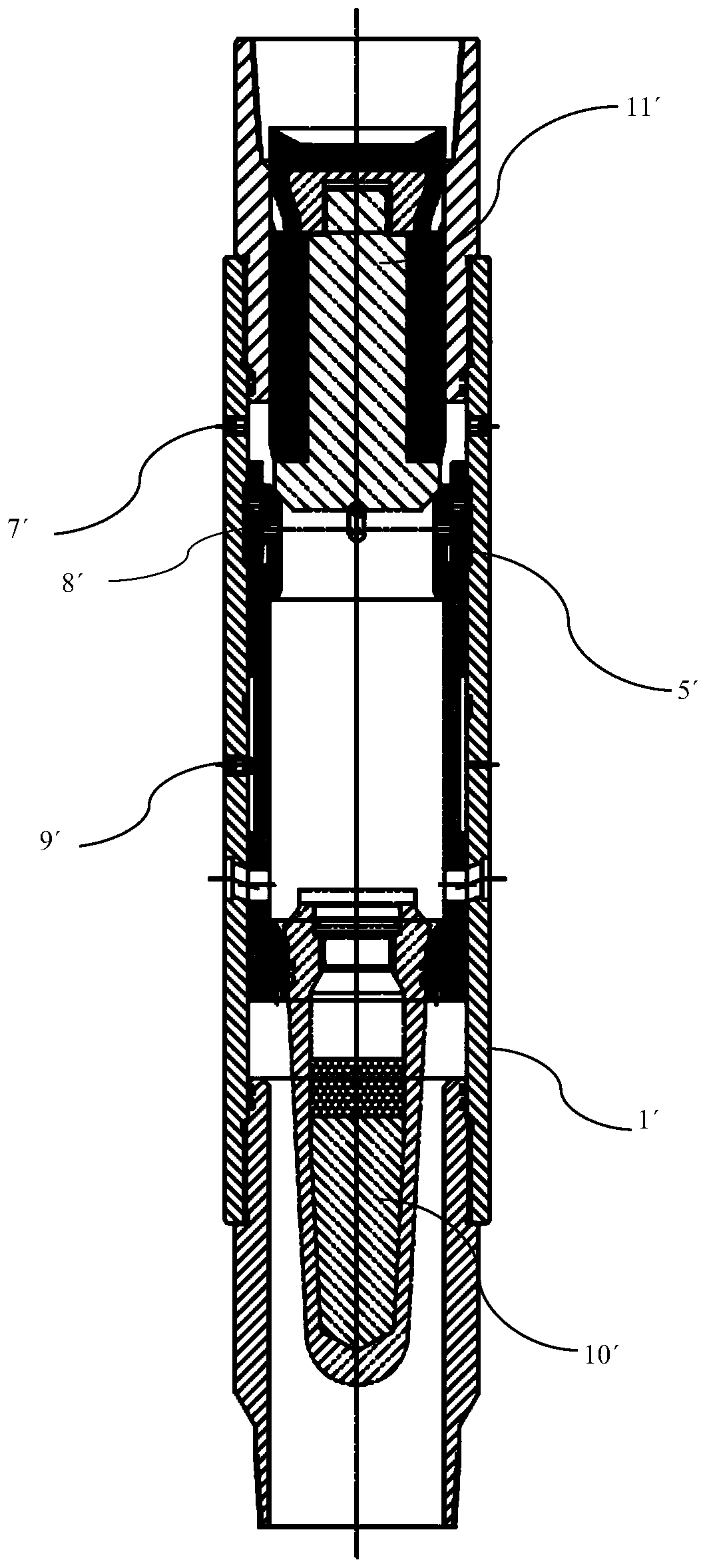
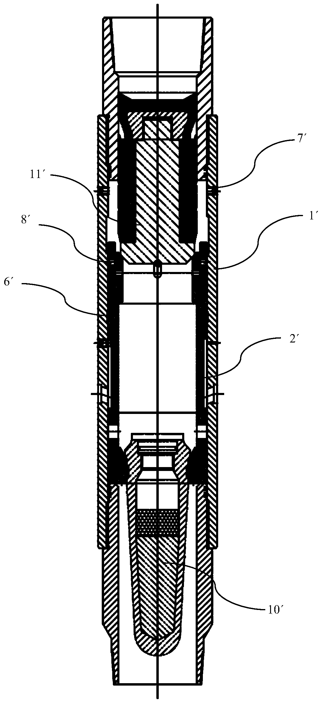
[0030] Exemplary aspects of the drillable graded hoop according to the present invention will now be described in detail with reference to the accompanying drawings. The drawings are provided to illustrate various embodiments of the invention, but the drawings are not necessarily to scale of particular embodiments and certain features may be exaggerated, removed, or partially sectioned to better illustrate and explain aspects of the invention. public content. Some components in the drawings can be adjusted according to actual needs without affecting the technical effect. Appearances of the phrase "in the drawings" or similar terms in the specification do not necessarily refer to all drawings or examples.

[0031] Certain directional terms used hereinafter to describe the drawings, such as "inner," "outer," "upper," "lower," and other directional terms are to be understood to have their normal meaning and refer to the drawings as viewed normally those directions involved. Un...


PUM


Abstract

The invention relates to the technical field of oil well sealing, in particular to a drillable stage hoop for stage well cementation, comprising a body, a first sldiing sleeve and a first connecting piece, wherein the body is configured to be substantially cylindrical and provided with a circulating hole in the side wall; the first sliding sleeve is arranged in the body and blocks the circulatinghole, and the first sliding sleeve is provided with a first sealing plug so as to seal the inner space of the first sliding sleeve; the first connecting piece is connected with the body and the firstsliding sleeve; the first connecting piece comprises a first fixing part and a first connecting part; the first connecting piece is constructed and arranged to be regularly disconnected at the joint of the first fixing part and the first connecting part after being subjected to force sufficient to break the first connecting piece, the first connecting part is contained in the first sliding sleeveafter being disconnected, and the first sliding sleeve moves in the body to open the circulating hole.

Description

technical field [0001] The invention relates to the technical field of oil well sealing, in particular to a drillable grading hoop for grading cementing. Background technique [0002] In the cementing process, the casing is generally lowered to the designed well depth, and cement slurry is injected into the casing and the wellbore annulus, and the annulus is sealed by the solidification of the cement slurry to prevent leakage between layer fluids, thereby protecting the production layer. , Strengthen the well wall, support the casing while preventing the layer fluid from corroding the casing, and establish safe drilling channels and oil and gas production channels. Cementing is an important link in the construction process of oil and gas wells. [0003] However, the existing cementing device and technology often have cementing failures during the cementing operation. Since the drillable grading hoop is operated at a position about 1500 meters downhole, and the operation of...

Claims


Application Information

Patent Timeline
IPC IPC(8): E21B33/13
Inventor 范波
Owner QINGDAO HAIFUAO IND TRADE
Why Eureka
Try Eureka