Monocular multi-view three-dimensional display method

A three-dimensional display, multi-view technology, applied in image communication, optics, instruments, etc., can solve problems such as focus-convergence conflicts

Pending Publication Date: 2019-05-21
驻景(广州)科技有限公司
View PDF6 Cites 11 Cited by
  • Summary
  • Abstract
  • Description
  • Claims
  • Application Information

AI Technical Summary

Problems solved by technology

[0003] The purpose of the present invention is to solve the focus-convergence conflict problem faced by the traditional stereoscopic technology, and to provide a three-dimensional display method of single-eye multi-view

Method used


Image

  • Monocular multi-view three-dimensional display method
  • Monocular multi-view three-dimensional display method
  • Monocular multi-view three-dimensional display method

Examples


Embodiment 1

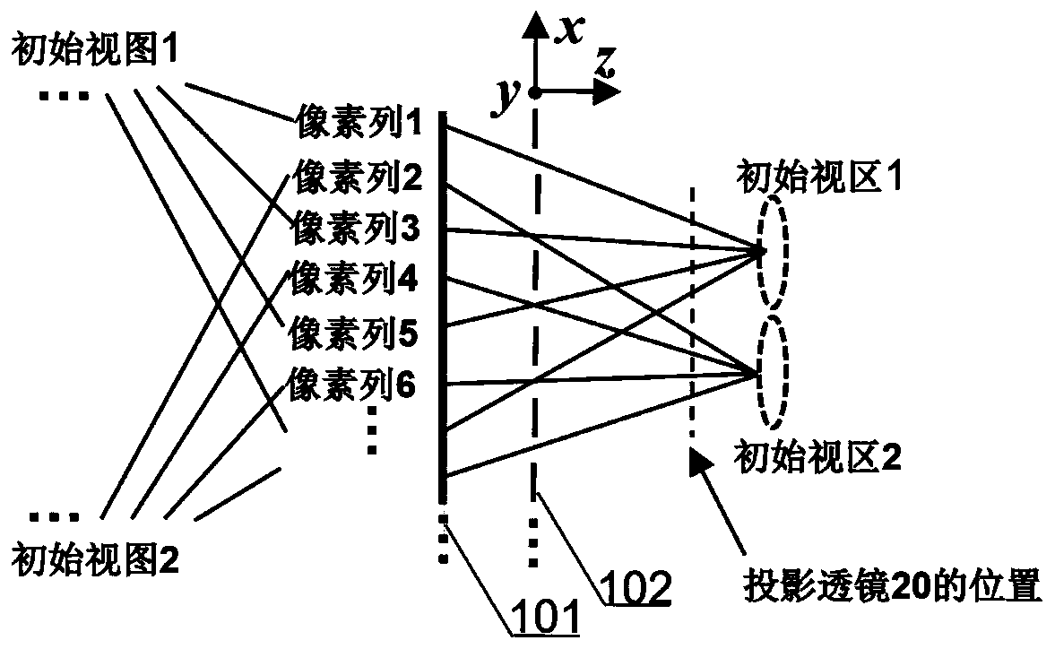
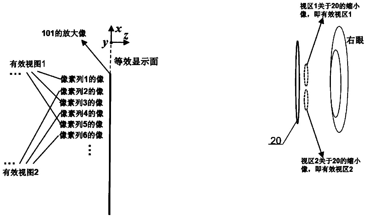
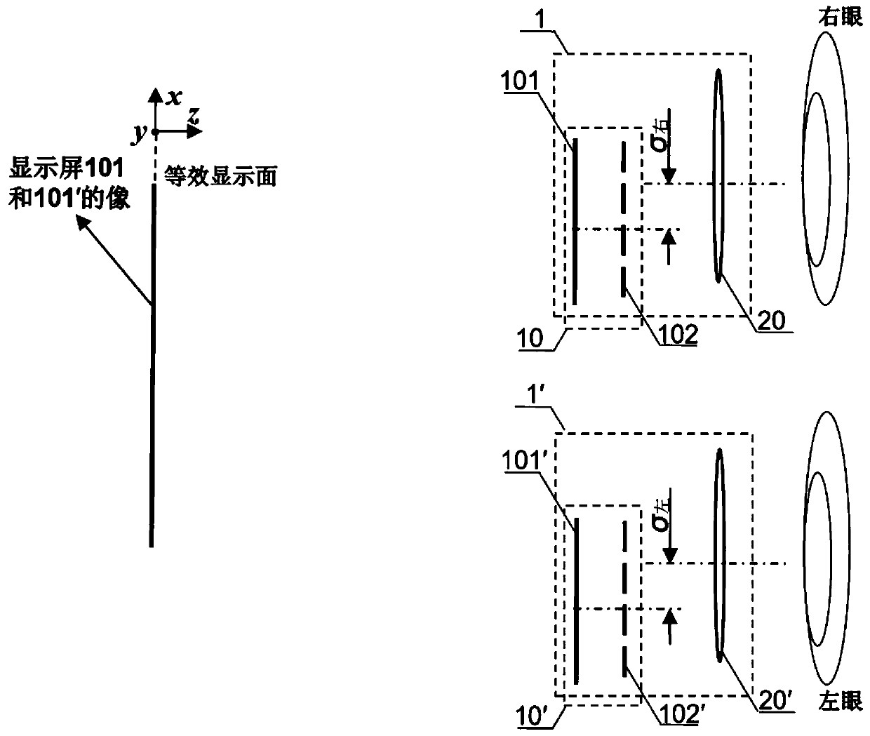
[0035] A three-dimensional display method for monocular multi-view, which needs to select a display unit 10 capable of generating k≥2 views (defined as initial views), and each initial view is visualized through a corresponding view area (defined as initial view area) . Taking k=2 as an example, the schematic diagram of its structure is as follows figure 1 (a) shown. Then set the projection lens 20 between the initial view and the initial viewing area, such as figure 1 (b) A magnified image and a reduced image are respectively formed for the initial view and the corresponding initial view area, and the two images are respectively defined as the effective view and the corresponding effective view area. Specifically, a display unit composed of a display screen 101 and a grating 102 attached thereto is used as an example for illustration, as figure 2 . After the light is split by the grating 102, the initial view displayed by the pixels in the odd columns on the display scre...

Embodiment 2

[0042] A single-eye multi-view three-dimensional display method, which selects a display screen 101" with k converging lights time-sequentially cyclically incident as the display unit 10". Such as Figure 6 As shown, simply take k=2 incident converging light as an example for illustration. The k=2 incident converging lights are respectively converged on the initial viewing area 1 and the initial viewing area 2, and are incident on the display screen 101 ″ at adjacent time points t and t+Δt, and the corresponding two initial viewing areas figure 1 and initial view figure 2 The display is refreshed synchronously. Then set the projection lens 20 between the initial view and the initial viewing area, such as Figure 7 , forming a magnified image and a reduced image for the initial view and the corresponding initial view area respectively, and the two images are respectively defined as an effective view and a corresponding effective view area, wherein the effective view is the ...

Embodiment 3

[0049] A single-eye multi-view three-dimensional display method selects the display screen 101"' where each pixel emits a directional light beam as the display unit 10"'. Simply take the formation of k=2 initial viewing areas as an example. Each pixel on the display screen 101"' has its own independent outgoing direction. both point to the initial viewport 2, such as Figure 8 shown. Then the odd column pixels load the initial view figure 1 Visible through the initial viewing area 1, even-numbered columns of pixels load the initial viewing area figure 2 Visible through initial viewport 2. Then, a projection lens 20 "' is placed between the display screen 101"' carrying the initial view and the initial viewing area, and the former becomes a magnified image, and the rear becomes a reduced image, such as Figure 9 shown. The display unit 10"' and the projection lens 20"' form a multi-view projection unit. The magnified image of the display screen 101"' is projected onto an...


PUM


Abstract

The invention discloses a monocular multi-view three-dimensional display method. A multi-view optical display structure with limited number of presented views is utilized, a projection lens is introduced between a display view of the multi-view optical display structure and a corresponding view area to amplify the display view, and the interval between adjacent views is reduced, so that two or more pieces of view emergent light information can enter one eye of an observer through two or more adjacent view areas to realize monocular multi-view presentation. The visual discomfort caused by focusing-convergence conflicts of the traditional three-dimensional display technology is avoided, and the visual area distribution area is expanded by arranging two or more multi-view optical display structures/projection lens pairs to cover the two eyes of the observer or provide a larger observation area for the two eyes of the observer.

Description

technical field [0001] The present invention relates to the technical field of three-dimensional image display, and more particularly, to a single-eye multi-view three-dimensional display method. Background technique [0002] Because two-dimensional display is difficult to clearly and accurately express the depth information of the third dimension, people have been working on the research of display technology that can display three-dimensional scenes - three-dimensional image display technology. However, the inherent focus-convergence conflict of the traditional stereoscopic 3D display technology will cause visual discomfort, especially in the field of near-eye 3D display. This visual discomfort is a bottleneck that hinders the popularization and application of 3D display. At present, starting from various technical routes, researchers are working hard to study technologies that can alleviate or eventually overcome this bottleneck problem. Contents of the invention [00...

Claims


Application Information

Patent Timeline
Patent Type & Authority Applications(China)
IPC IPC(8): G02B27/22H04N13/363
Inventor 刘立林滕东东
Owner 驻景(广州)科技有限公司
Why Eureka
Try Eureka