Electronic device and display control method

A technology for electronic equipment and display area, which is applied to TVs, color TVs, electrical components, etc., can solve the problems of uneven light distribution, no supplementary light mechanism, too dark, etc., to achieve the effect of supplementary light

Inactive Publication Date: 2019-05-28
AU OPTRONICS CORP
View PDF0 Cites 11 Cited by
  • Summary
  • Abstract
  • Description
  • Claims
  • Application Information

AI Technical Summary

Problems solved by technology

In the current side-type backlight module, the light distribution near the perforation is uneven. For example, when using a side-type light source, there will be a bright band around the semicircle on the side of the perforation close to the side-type light source, while the perforation is far away from the edge of the side-type light source. There will be a dark band around the semicircle on the other side, so the border of the perforated design is prone to produce bright and dark bands, resulting in uneven brightness around the camera in the screen
When the camera shoots images in a dark environment, it will be too dark to lose details or be distorted, and it needs to be supplemented with light. In the existing technology, the front camera embedded in the screen does not use the supplementary light mechanism due to design limitations.

Method used


Image

  • Electronic device and display control method
  • Electronic device and display control method
  • Electronic device and display control method

Examples


Embodiment Construction

[0029] Embodiments of an electronic device and a display control method thereof according to the present invention will be described below with reference to related drawings. For ease of understanding, the same components in the following embodiments are described with the same symbols.

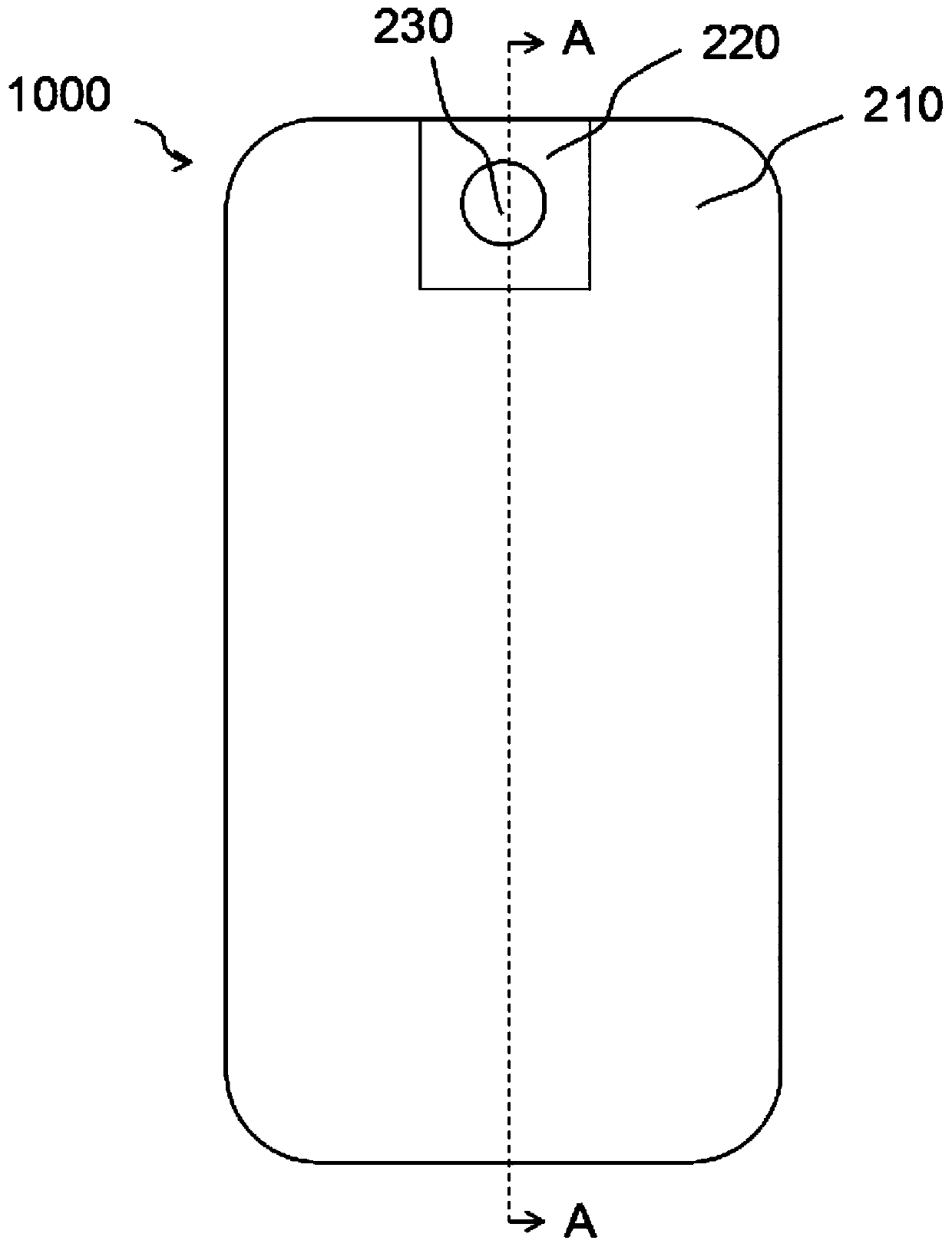
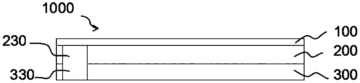
[0030] see Figure 1A and 1B As shown, a top view and a cross-sectional view of an embodiment of an electronic device 1000 of the present invention are disclosed. The electronic device 1000 includes a cover layer 100, a liquid crystal display layer 200, and a backlight module 300. The liquid crystal display layer 200 is arranged on the cover layer 100 and the backlight module. Between modules 300. The liquid crystal display layer 200 has a display area 210 , a supplementary light area 220 and a first through hole 230 , and the supplementary light area 220 is located around the first through hole 230 . At least the area of ​​the cover layer 100 corresponding to the display area 210 and the su...


PUM


Abstract

The invention provides an electronic device which comprises a liquid crystal display layer, a backlight module and a camera. The liquid crystal display layer comprises a display area, a light supplement area and a first through hole, and the light supplement area is located around the first through hole. The backlight module is provided with a second through hole corresponding to the first throughhole. The camera is arranged in a space formed by the first through hole and the second through hole. No filter layer is arranged or the pixel area is increased in the light supplement area to improve the light transmittance of the light supplement area of the liquid crystal display layer. A light guide plate is provided with scattering particles and microstructures corresponding to the light supplement area to improve the light output efficiency of the light supplement area. The luminous intensity of a direct-down backlight source corresponding to a light source of the light supplement areais larger than that of a light source of the display area to improve the light output intensity of the light supplement area. Thus, the electronic device overcomes the defect that bright and dark bands appear around an original through hole, and original modules of the light supplement area of the electronic device are designed to realize the double functions of photographic light supplement and illumination.

Description

technical field [0001] The present application relates to the technical field of electronic equipment, in particular to an electronic equipment and a display control method. Background technique [0002] In order to realize the Selfie function, there is always a front camera on the screen. In order to maximize the screen area, the front camera is integrated into the display area of ​​the screen, which requires the display to have a perforated design. In the current side-type backlight module, the light distribution near the perforation is uneven. For example, when using a side-type light source, there will be a bright band around the semicircle on the side of the perforation close to the side-type light source, while the perforation is far away from the edge of the side-type light source. There will be dark bands around the semicircle on the other side, so the border of the perforated design will easily produce bright and dark bands, resulting in uneven brightness around th...

Claims


Application Information

Patent Timeline
Patent Type & Authority Applications(China)
IPC IPC(8): G02F1/1333G02F1/13357H04N5/225G03B15/02G02F1/1335G02B6/00G02F1/133G09G3/34
Inventor 吴濠濠
Owner AU OPTRONICS CORP
Why Eureka
Try Eureka