Machining method for crankshaft hole

A processing method and crankshaft hole technology, which is applied in the field of crankshaft hole processing, can solve problems such as easy vibration, overhang elongation, and strong limitations, and achieve the effects of achieving flexibility, improving processing efficiency, and improving processing efficiency

Pending Publication Date: 2019-06-04
SAIC GENERAL MOTORS
View PDF13 Cites 0 Cited by
  • Summary
  • Abstract
  • Description
  • Claims
  • Application Information

AI Technical Summary

Problems solved by technology

Due to the use of special machine processing, this processing method can not meet the needs of flexible production, nor can it perform automatic tool compensation, which has strong limitations.
[0004] The machining center adopts the method of turning around the hole to process the crankshaft hole: because the overhang of the crankshaft hole boring tool is long, and the length of the crankshaft hole is generally greater than 300mm, the two-end boring scheme is adopted. Since the boring bar is in a cantilever state, the overhang is relatively large. Long, poor rigidity and strength, easy to cause vibration, difficult to guarantee the dimensional accuracy and shape accuracy of the bored crankshaft hole

Method used


Image

  • Machining method for crankshaft hole
  • Machining method for crankshaft hole
  • Machining method for crankshaft hole

Examples


Embodiment Construction

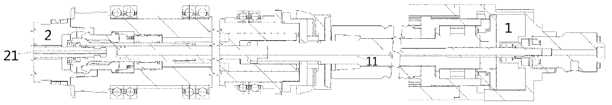
[0021] According to an embodiment of the present invention, in the crankshaft hole machining method, the movement of the spindle expander rod drives the boring tool expander bar of the expandable boring tool in the machining center to realize the expansion and retraction of the boring tool blade. Such as figure 1 As shown, the spindle expander bar 11 of the spindle 1 and the boring tool expander bar 21 of the expandable boring tool 2 are connected, for example, through the cooperation of a key and a keyway. By using the movement of the main shaft to drive the boring tool expanding bar of the expandable boring tool, the automatic retracting and expanding of the boring tool blade, automatic tool change and automatic diameter compensation can be realized, which improves the processing efficiency, processing quality and Processing stability realizes the flexibility of processing line production and improves processing efficiency.

[0022] According to one embodiment of the presen...


PUM


Abstract

The invention discloses a machining method for a crankshaft hole. According to the method, a boring cutter expansion bar of an unfolding type boring cutter is driven by the movement of a main shaft cutter expansion bar in a machining center so as to realize expansion and retraction of a boring cutter blade. The method has the advantages that the boring cutter expansion bar of the unfolding type boring cutter is driven by the movement of the main shaft cutter expansion bar, so that automatic retraction and expansion of the boring cutter blade, automatic cutter changing and automatic diameter compensation can be realized, and therefore the machining efficiency, the machining quality and the machining stability are improved, the flexibility of the machining line production is realized, and the machining efficiency is improved.

Description

technical field [0001] The invention relates to the field of automobiles, in particular to a method for machining a crankshaft hole. Background technique [0002] The crankshaft hole is an important hole system of the engine skeleton cylinder block and the processing design and positioning reference. Its processing quality directly affects the assembly accuracy and overall operation performance of the engine, which is a difficult point in machining. [0003] Crankshaft hole processing of special processing machine tool: In order to ensure the machining shape accuracy and position accuracy of the crankshaft hole, the combined boring tool is used on the special processing machine tool for semi-fine boring and fine boring processing, and the crankshaft hole boring tool is guided and supported to ensure Shape accuracy and position accuracy of crankshaft hole machining. Due to the use of special machine processing, this processing method can not meet the needs of flexible produc...

Claims


Application Information

Patent Timeline
Patent Type & Authority Applications(China)
IPC IPC(8): B23B41/00B23B35/00
Inventor 吕昆仑吴俊卢壮
Owner SAIC GENERAL MOTORS
Why Eureka
Try Eureka